Combining Part Assemblies with Additive Manufacturing
How to find the right opportunities to consolidate multi-part assemblies into single components with industrial 3D printing
Additive manufacturing, or industrial 3D printing, is moving from its original prototyping function into the realm of final production parts. New frontiers of part design are being opened that even 10 years ago would not have been possible.
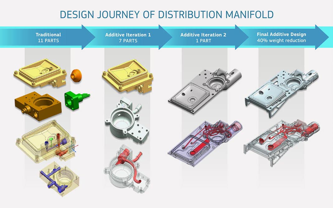
One of the most commonly cited benefits of additive manufacturing is the ability to consolidate existing part assemblies made from many pieces into a single part. If you’ve flown on a newer airplane you may have already experienced this without knowing it. The most famous example from the aerospace industry is GE’s additively manufactured fuel nozzle for CFM International’s LEAP aircraft engine. The nozzle had been an engine component made from 20 parts that was turned into one, with 25% weight reduction.
However, undertaking such a design project is daunting, and all too often engineers embark on the journey either to find that the result doesn’t save as much money as they thought, or that they can’t meet requirements they are accustomed to with traditional manufacturing.
The problem isn’t the engineer or the technology, but often the selection of assemblies to combine and a misunderstanding of how to do it effectively. This guide explores how to find opportunities to move multi-part assemblies toward consolidated additive manufacturing in direct metal laser sintering (DMLS), selective laser sintering (SLS), and multi jet fusion (MJF), but also how to achieve a result that is more cost effective and higher performing than other manufacturing methods. Beyond the additive technologies that are showcased in this guide, we also offer three other 3D printing processes at Protolabs: Stereolithography (SLA) and PolyJet.

When to Combine Assemblies for Additive Manufacturing
Typically, it is not enough to think in terms of combining two parts—ideally, think in terms of 20-plus parts if you can. The more parts being combined, more than likely the greater the savings. If pieces are fixed once assembled, that may be an opportunity for consolidation. The more challenging to assemble as it exists now, the better. In additive manufacturing, complexity is often free—the most successful parts take advantage of this axiom as much as possible.
The best-case scenario, and what every engineer should strive for, is to not just find cost savings but also improved part performance with additive manufacturing. A combined assembly will typically have fewer points of failure and added strength from a unified part. Look for applications where either of these would be big wins and not small. Internal cooling channels are easy to incorporate as well, potentially giving way to benefits such as reduced part fatigue. Fulfill your full design wish list—the unmanufacturable can be suddenly made possible, so create the best part you can.
To properly assess the benefit of a consolidated assembly, look beyond the basic sourcing cost of the parts being replaced—the savings should go much deeper. Other things to consider include:
- Elimination of assembly: This includes reduced labour, inventory, fixturing/tooling, and manufacturing floor space dedicated to your final product. Assembly inspection is also reduced; no opportunities for assembly errors.
- Fewer points of failure: Maintenance costs are reduced long-term, and you can stock fewer replacement parts. If needed, low-volume replacements can be made quickly and cost effectively.
- Lower operation costs: Part optimisation from design freedom—thanks to additive manufacturing—improves product performance, enabling enhancements such as part lightweighting and better thermal performance.
The best opportunities for conversion to 3D printing from other manufacturing methods are often high-value or high-performance situations in which existing solutions are constantly at the brink of failure, underperforming, or see significant cost in production beyond the manufacture of basic components. Parts and assemblies that are currently being manufactured without significant difficulty likely will not be good opportunities to move toward additive manufacturing—machining a few metal components for a relatively simple assembly, for example. If it isn’t broken, don’t try to fix it!
How to Combine Assemblies For Additive Manufacturing
Since reducing assemblies equates to cost savings in a more nebulous sense, it is often easier said than done. At a basic level, you may be able to take multiple traditionally made parts in your 3D CAD assembly file and export them as one piece to create a solidified “Frankenstein” part, which theoretically could be produced with additive manufacturing. We often see these and are asked “can you make this?” to which the answer is often “Yes!” However, this doesn’t mean the result will be cost effective, of high quality, or a performance improvement. Just because additive manufacturing provides near unlimited design freedom, this doesn’t mean every part is cost effective or well-suited for the technology.
It may be worthwhile to think about your application at its most basic level and ask what the fundamental design requirements are outside of manufacturability concerns, and work backwards from there. Designing effectively for additive manufacturing often requires “unlearning” the manufacturing limitations baked into your mind from years of working within them. If an aspect of your additive part exists because in a legacy version it was typical of its manufacturing method, it’s worth asking if it’s necessary anymore.
In a very general sense, material volume equals cost in additive manufacturing. Get rid of anything nonessential for functionality. But remember one of the most foundational rules of additive manufacturing: complexity is free. The key to a cost-effective part is often to add value by making your design as high performance as it can be without the constraints of traditional design.
That said, while additive manufacturing provides design freedom unrivaled by other manufacturing methods, it is not without its own rules and guidelines. Additive manufacturing provides a path to production for parts that could never have been made before, including optimised parts made via generative design. It is worth keeping in mind that while an organically shaped part generated by 3D topology optimisation software may be theoretically the best possible solution for a given loading condition, this does not mean the part is well-designed for additive manufacturing.
This is especially true when considering technologies that may require support material to form, such as DMLS. These parts may have significant overhangs requiring added support material in the build to form, which increases print time and labour in finishing. Hollow parts may need careful examination of internal overhangs or “bridges,” to prevent added inaccessible internal supports from being required. We recommend reviewing our DMLS design guidelines to learn more about design requirements at Protolabs.
However, if you are designing for a technology such as SLS or MJF, which use the powder cake itself to support the part, no need to worry. In this case the only real concern is escape holes for powder removal (as applicable). Clips, latches, and snap fits are commonly made from durable materials within these technologies. DMLS materials require support materials to form. Generally, clips, latches, and snap fits are designed with assembly of multiple traditionally manufactured components in mind. With SLS and MJF, engineering grade nylons (filled and unfilled), and polyurethanes can manufacture these types of parts in one assembly. Stereolithograhy (SLA) materials are not as ideal for these types of parts due to their brittle nature. However, if you are after fit and form, and not as interested in long-term durability and function, SLA can still be an option for you.
A couple of design rules should be considered for clips, latches, and snap fits that are built as one part. Know that these parts experience the greatest stress when they are being connected, so ensure you incorporate fillets into your design which can help alleviate some of the encountered stress. Incorporating living hinges into clips and latches can also work in your favour. Here’s a living hinge guide to help you get started. Finally, do consider that how the parts are oriented as they are being manufactured can positively or negatively influence performance. Parts should be oriented in a way that reduces stress on the connection points of friction. We can help you determine the right part orientation in any of our technologies so your design goals are achieved.
Resources are available to help guide you toward sound design principles for any additive technology you are thinking about, or get in touch with one of our applications engineers to discuss your design.
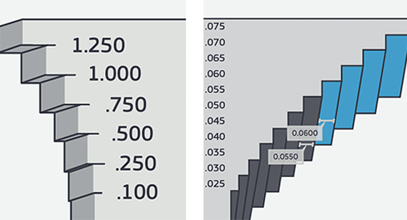
Considering Tolerances for Additively Manufactured Parts
Determining the tolerances possible for any one additively manufactured part can be difficult, since every part responds differently to the thermal stress during the build. In DMLS, tolerances of +/- 0.1 mm to +/- 0.2 mm + 0.005 mm/mm are expected and achieved. For MJF tolerances of ±0.25mm plus ±0.002mm/mm can typically be achieved. For SLS Typically, expected tolerances on well-designed parts are +/-0.2mm, plus +0.002mm/mm. For TPU-88A Black, tolerance of ± 0.3mm plus ± 0.002mm/mm can be expected (for parts bigger than 100 mm in this material, tolerance will be ± 0.3% of nominal dimension). For PA 12 Flex Black, tolerance of ± 0,35mm plus ± 0,002mm/mm can be expected (or else, for bigger parts, ± 0,2% of nominal dimension). Warp or shrink-prone parts can exceed these ranges. Every geometry is unique and behaves differently under the stress of the build. If tight tolerances are required for an additively manufactured part, they generally must be dialed-in with repeated upfront builds or post-machined.

However, a well-designed additive part may still improve the accuracy of what otherwise would be a complex assembly by eliminating tolerance stacking. Part of transitioning to additive manufacturing for a product may include letting go of the tight tolerances on a per-part level that you’re used to expecting. In this case, it’s important to not compare apples to oranges—don’t ask if the new part can be as accurate as the parts it is replacing, ask if it can be as accurate as all of them in the aggregate.
Another difficult question worth asking: How do you inspect such a complicated part? It may require innovative inspection processes depending on the complexity. Again, keep in mind that while checking the part may prove more difficult than existing inspections, it is concentrated into a single part rather than many. A limited dimension drawing for inspection should only include dimensions truly critical for functionality. In theory, there should be less of these overall since the newly consolidated assembly will have fewer points of interface. The old interface points are inside the new part.
Finishing Options for Additive Parts: Machining, Threading, Polishing
Keep in mind post-processing considerations for additive parts because sometimes these parts require tighter tolerances or better surface finishes than as-printed additive parts can provide. It is not uncommon for additive parts to receive post-machining on critical features such as gasket interfaces and other precise fits. However, effective and cost-efficient post-build operations require careful consideration to avoid losing all the benefit of combining your assembly in the first place. Try to limit post-machining where possible—essentially you are paying for both traditional and additive manufacturing at this point, and the applications where this makes economic sense often involve complex, high-value geometries that truly cannot be made any other way.

Additive parts present unique machining challenges compared to traditional parts from stock material. One of these challenges is surface roughness. An as-printed surface is rougher than typical stock, which can increase measurement variability when creating a reference frame. This may lead to reduced accuracy for machined features referencing an as-printed surface, or you can first machine the datum reference. Of course, at some point the first cut has to be on an as-printed part. Large flat surfaces on the part that can be fixtured easily typically work best as initial datum planes. Features printed in the same plane tend to print very accurately with respect to each other, allowing external planes to stand-in as references when trying to machine features with respect to internal geometry.
If the extent of your post-machining need is functional threads, one great cost-saving option is to include threads in the printed model and then chase them after the build with a tap or die. Threads will be rough and likely not fully functional as printed, but they will be accurate enough to guide the tool into place for cutting usable threads. This typically requires minimal tooling and is a great option for when a loose thread class or locational tolerance is acceptable.
Finally, there is the issue of surface finish improvement. DMLS parts are roughly equivalent to cast parts in terms of surface finish, in the ballpark of Ra 4-23µm (depending on material, orientation and resolution). The best option for improving on this likely depends on the application and quantity of parts needed. DMLS parts take to hand polishing very well, but this is a fully manual process more similar to jewelry making than industrial manufacturing. Polished surfaces can achieve near-mirror finishes, but because of the handwork involved it is difficult to maintain tight dimensional tolerances or scale to higher quantities. For functional showpieces however, this can be a great option. SLS and MJF parts have similar wisdom, where surface finish improvements typically involve a labour-intensive series of sanding, priming, more sanding, and painting to achieve a smooth surface.
There are options out there for global surface finish improvements to parts, however these often require upfront setup and R&D costs to hone the process for an individual geometry. These services are typically available only for production parts and not viable for low-quantity prototypes.
Considering Scalability for Additive Manufacturing
All of this work to convert or create a new part for additive manufacturing may not make sense unless it is a high-value component or there is need for low-volume production. Additive manufacturing allows for low cost of entry and accelerated manufacturing lead times, however unit pricing reaches a floor much earlier than other manufacturing methods. While historically the break-even point for parts made traditionally vs. additively has been near quantities of 10 to 100, new advances and technologies are starting to push this range closer to 100 to 1,000 or higher in some cases.

Ultimately the break-even cost is highly dependent on the size and complexity of a given part. If your additive part is combining many traditionally made parts from what otherwise would be a complex assembly, additive manufacturing can easily make economic sense at almost any scale.
In general, additive parts start to see their lowest price per part at whatever quantity can fit together on a single-build platform. Parts built together share recoat time and reduce machine turnover, leading to efficient production. Small parts can be built in batches of 1,000 parts or more in extreme cases; for larger parts approaching the entire size of a build chamber, the unit price floor may be essentially quantity 1.
For small parts printed in high-quantity builds, the largest cost driver may be finishing labour. While the parts may require next to no time to form in the machine, each one requires added support material to allow features to form via DMLS. Unless parts can be built without any added supports and are simply cut off from the build plate via wire EDM, some labour will be needed for every part to remove added supports. Designing features to form self-supporting parts is a great opportunity to reduce cost for high-volume additive manufacturing. For parts made via SLS or MJF, finishing involves removing caked-on powder from tight corners, slots, or holes. Simplifying surfaces for easy cleaning post-build can reduce labour time and cost.
Larger parts that are the result of a combined assembly, for example, may see their price driven mostly by the total material volume of the part. Thick simple cross sections may not add cost in traditional manufacturing, but they add significant cost in additive manufacturing by increasing the draw time of the build. Furthermore, they may lead to a lower quality part by increasing the risk of warpage in the build. Lightweighting parts for additive manufacturing may not only improve performance, but in most cases it is a cost-saving exercise as well.
At Protolabs, we build large-format metal parts using this GE Additive Concept Laser X Line 2000R machine. It is the largest powder-bed metal additive system in the world, and can build production-grade metal parts as large as EOS M300 which is 300 x 300 x 400 mm (normal resolution) aluminium only
When to Stick With Traditional Manufacturing
Not every application lends itself to additive manufacturing. Low-value, high-quantity parts will always be better suited to other manufacturing methods. It is very rare that a part already being produced successfully via other manufacturing methods can be shifted to additive manufacturing without any changes and made at lower cost.
For a machined part to translate directly to additive, it must be extremely difficult or expensive to machine as-is. Think in terms of chips on floor—for additive to make sense for an existing part, it would be for one where currently more material is milled away than remains in the end result. When combining two (or more) machined parts into a single additive part, they likely both need to be difficult to produce individually. Ideally, they should be combined in a way that meaningfully improves your product in value-added ways that could be achieved in no other way. In most cases, if it can be machined it should be machined.

However, size and material are important factors for parts that may be more cost effective than one may think. Very small parts that typically would require micromachining may be shockingly affordable when made via DMLS since cost is tied to material volume. A part which only weighs a few ounces will likely be among the cheapest of DMLS parts, even if it’s extremely complex from a design standpoint. DMLS is also unfazed by challenging materials to machine like Inconel or titanium. The price for a given machined part made from titanium vs. aluminium may be radically different; with additive manufacturing, the price will be more comparable.
DMLS can also serve as a great bridge for prototyping cast parts—but again, it’s rare that DMLS will remain competitive from a price perspective against casting long term. The best use case here can be low-volume specialty variants for custom jobs that don’t quite justify casting, or where long lead times to get first parts in hand won’t do.
On the plastics side, scale and again, complexity, is key. If your product need is expected to be well over 1,000-plus parts, you’re likely best off finding a way to get your part suitable for injection moulding. Typically the use cases for additive plastics at higher production quantities involve scenarios where you are getting a very significant reduction in part count and assembly labour, along with improved performance. Drones are a great example of this—an entire chassis for a drone can be printed as a single piece, lightweighted for optimal performance, and no assembly required. The footwear industry is also investing heavily these days in additive manufacturing for things like customised midsoles.
In the end, moving an existing assembly toward consolidated additive manufacturing can be hard. Additive is a powerful solution when applicable, but not every situation calls for it. That’s why it’s helpful to use a supplier that does both. At Protolabs, we aren’t afraid to tell you if your application is better suited for another digital manufacturing option like machining or moulding. If you’re new to additive and looking to figure out how it works, applications engineers are available to talk about your design and product. Contact one of them at +44 (0) 1952 683047 or at [email protected].
 Email [email protected] with your name, title of activity, and completion date to receive your certificate