

Design for Mouldability
Volume 1: A Rapid Injection Moulding Reference Guide for Product Designers and Engineers.
Designing plastic parts for mouldability has always been important for traditional injection moulding processes, but it’s particularly beneficial during rapid injection moulding to ensure speed and quality remain constant during manufacturing. This guide examines many of the important design considerations that are encountered during injection moulding part design and product.
- What is Rapid Injection Moulding?
- Applications of Rapid Injection Moulding
- Wall Thickness
- Cored Geometry
- Recommended Wall Thickness
- Warp
- Sharp Corners
- Ribs
- Bosses
- Draft
- Core-cavity
- Deep (Milling) Impact
- Texture
- Straight-Pull Mould
- Side-Actions
- Bumpoff
- Pickouts
- Steel Core Pins
- Text
- Tab Gate
- Self-Mating Parts
- Tolerance
- Choosing a Material
- Select Colours
- Resin Additives
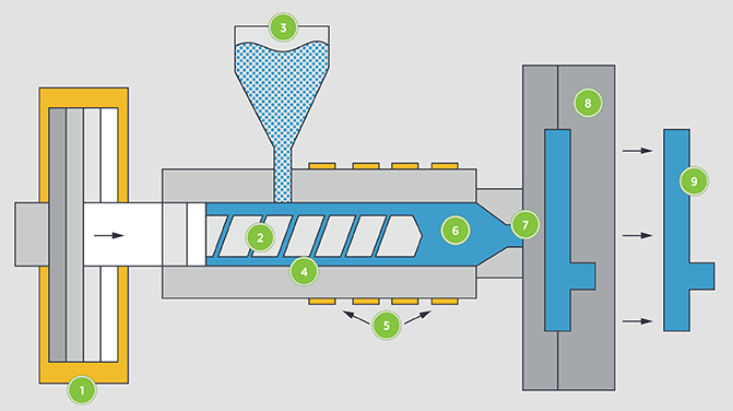
What is Rapid Injection Moulding?
Rapid injection moulding a technology-driven process that leverages manufacturing automation. CAD models are sent directly to the production floor where mould milling begins, but in most cases, moulds are fabricated from aluminium, not steel. This allows for faster and most cost-effective tooling when compared to traditional steel moulds.
There are number of surface finish options available and capabilities include side-action and hand-load inserts as well as simple overmoulding and insert moulding. Selective use of electrical discharge machining (EDM) is applied to improve mould features like corners and edges. The result is part production within a few weeks versus months when compared to traditional injection moulding methods.
Applications
- Iterate quickly with quick-turn prototypes
- Test functionality during product development with production-grade parts
- Test multiple materials
- Test multiple CAD models
- Make quick iterations
- Bridge tooling
- Implement bridge tooling
- Manage demand volatility
- Get thousands of parts within days
Industries
- Medical
- Automotive
- Electronics
- Aerospace
- Consumer Products
- Bridge tooling
- Appliance
- Lighting
- Marine
Let's Get Absolute
Recommended wall thickness by resin.
| Resin | Recommended Wall Thickness (mm) |
|---|---|
| ABS | 1.14 - 3.50 |
| Acetal | 0.64 - 3.05 |
| Acrylic | 0.64 - 3.81 |
| Liquid Crystal Polymer | 0.76 - 3.05 |
| Long-fibre Reinforced Plastics | 0.90 - 2.54 |
| Nylon | 0.76 - 2.92 |
| Polycarbonate | 0.11 - 3.81 |
| Polyester | 0.64 - 3.17 |
| Polyethylene | 0.76 - 5.08 |
| Polyphenylene sulfide | 0.51 - 3.81 |
| Polypropylene | 0.64 - 3.81 |
| Polystyrene | 0.89 - 3.81 |
Note: These are general guidelines, subject to part geometry and moulded construction. Larger parts shouldn’t be designed with the minimum wall thickness.
Tip: Protolabs’ general rule for wall thickness is 0.040–0.140.
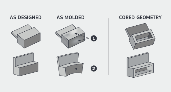
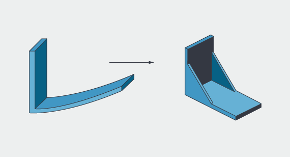
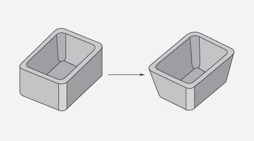
A Warped Personality
Eliminate sharp transitions that cause moulded-in stress.
Design 3D structures that support themselves.
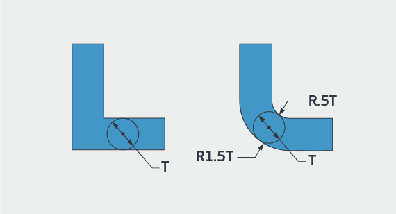
Get the Stress Out
Sharp corners weaken parts.
- They cause moulded-in stress from resin flow.
- They form a stress riser in your application.
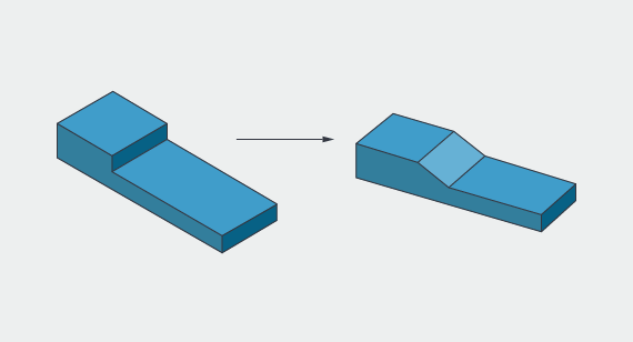
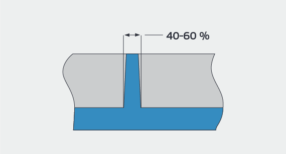
Give ’Em a Good Ribbing
To prevent sink, ribs should be no more than 60% of the wall’s thickness.
Tip: If Protolabs asks for greater wall thickness on your 40–60% T-wall, consider increasing your T-wall to compensate for this increased thickness to reduce the risk of sink.
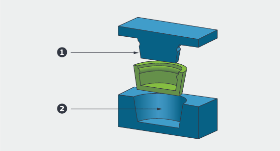
Core-cavity
When you draft, use core-cavity instead of ribs if you can. It allows you to have constant wall thickness rather than walls with a thick base. We can mill moulds with better surface finish and deliver better parts faster.
Tip: This option is faster and less expensive to manufacture.

Bumpoffs
A bumpoff is a small undercut in a part design that can be safely removed from a straight-pull mould without the use of side-actions. Bumpoffs can be used to solve some simple slight undercuts, but are sensitive to geometry, material type.
Tip: Moulds can be made core-cavity, allowing room for the part to “bumpoff” after the mould opens.
Pickouts
A pickout is a separate piece of metal that is inserted into the mould to create an undercut. It is ejected with the part, then removed by the operator and re-inserted in the mould.
Tip: Using a pickout overcomes many shape and positioning restrictions, but is more costly than sliding shutoffs, or using a side-action.
Watch Your Penmanship
Choose a sans serif font where the smallest feature is at least 0.020 in. thick. Serif fonts have small tails which are often too small. Text that is raised above the part is better. We cannot polish around it if the text is cut into your part.
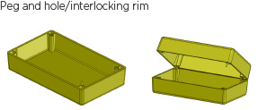
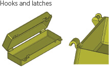
Self-Mating Parts
Identical parts that flip over and mate to themselves are possible and save the cost of a second mould.
- Peg and hole
- Interlocking rim
- Hooks and latches
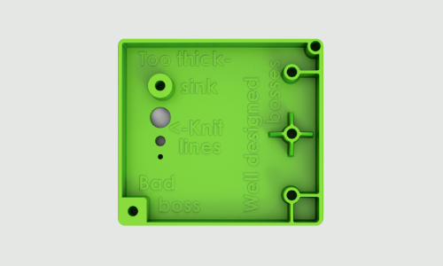
Good and Bad Bosses
- Don’t create thick sections with screw bosses.
- Thick sections can cause sink and voids in your part.
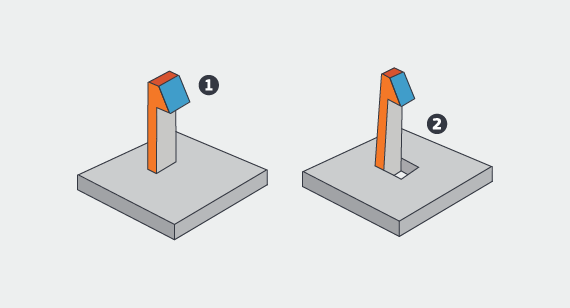
Don’t Be a Draft Dodger
Draft (slope the vertical walls) as much as possible — this makes it easier to eject parts without drag marks or ejector punch marks. You get better parts, faster.
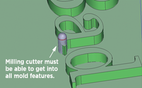
Deep (Milling) Impact
Draft the part as much as possible. This allows us to make deeper features for you. Draft allows us to reduce tool chatter and cosmetic defects when milling deep walls. If you can fit it in, use 1 degree of draft or more. On core-cavity designs, try to use 2 degrees or more. A rough rule of thumb is 1 degree of draft for each of the first 2 inches of depth. From 50mm to 101mm of depth, either 3 degrees of draft or a minimum of 3mm thickness may be required.
Texture
Protolabs can add bead-blast texture to the mould for your parts. Light texture requires 3 degrees of draft minimum on vertical walls. Medium texture requires 5 degrees.
Straight (Pull) Shooter
Sliding shutoffs are your friend — these features can be made in a straight-pull mould. They do require 3 degrees of draft but save significant money over side-actions.
Side-Action for Undercuts
Side-actions can form undercuts on the outside of your part. Undercuts must be on or connected to the parting line. They must be in the plane of the parting line. Undercuts must be connected and perpendicular to the direction the mould is opening.
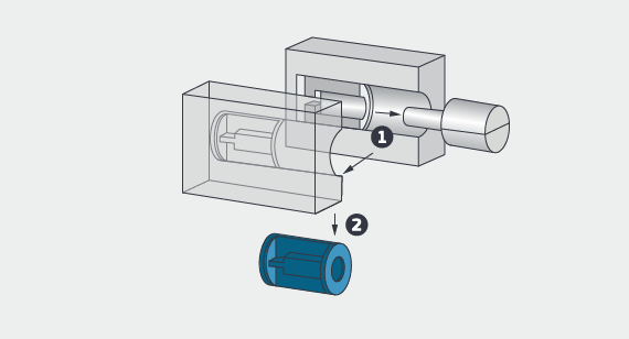
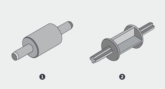
High-Aspect-Ratio, Small Diameter Holes
These holes can be made with steel core pins in the mould. A steel pin is strong enough to handle the stress of ejection and its surface is smooth enough to release cleanly from the part without draft. There shouldn’t be any cosmetic effect on the resulting part; if there is, it will be inside the hole where it won’t be seen.
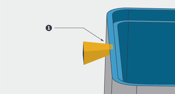
Open the Floodgates
Thin edges restrict flow and can break during gate trimming. We need somewhere thick to gate into your part. There may be alternatives, so please contact one of our customer service engineers at +44 (0) 1952 683047 or [email protected].
Be Tolerant
- Protolabs can hold about 30.08mm machining accuracy.
- Shrink tolerance depends mainly on part design and resin choice. It varies from 0.05mm per 25.4mm for stable resins like ABS and polycarbonate to 0.65mm per 25.4mm for unstable resins like Santoprene.
- There are techniques for getting the most accuracy out of our process. Please contact a customer service engineer on +44 (0) 1952 683047 or [email protected].
It’s a Material World
When choosing a material for your part, relevant properties might include mechanical, physical, chemical resistance, heat, electrical, flammability or UV resistance. Resin manufacturers, compounders and independent resin search engines have data online. For resin links, visit protolabs.co.uk/materials.
Commodity Resins
Polypropylene
- Soft
- Tough
- Cheap
- Chemical resistant
- Makes good living hinges
Polyethylene
- Soft
- Tough
- Cheap
- Chemical resistant
- High Density
- Low Density
Polystyrene
- Hard
- Clear
- Cheap
- Brittle but can be toughened
Colours
No colour-matching, salt/pepper 3% mixture for most stocked colourants, re-compounded material/colourants or customer supplied colourants.
Engineering Resins
ABS
- Inexpensive
- Impact Resistant
- Equipment and handheld housings
- Susceptible to sink
Acetal
- More expensive
- Strong
- Good lubricity and machinability
- Very sensitive to excess wall thickness
LCP
- Very expensive
- Very strong
- Fills very thin parts
- Weak knit lines
Nylon
- Reasonable cost
- Very strong
- Susceptible to shrink and warp, particularly glass-filled
- Absorbs water - dimensional and property change
Polycarbonate
- Moderate cost
- Very tough
- Good dimensional accuracy
- Susceptible to chemical stress cracking, voids
PBT, PET, PPS, PSU, PES, PEI, and many others
Select Colours
Stock colours from the resin vendor are typically black and natural. Natural might be white, beige, amber or another colour. Semi-custom colours are created when colourant pellets are added to natural resins. Click here to view available colours. There is no added charge for our inventory colours. They may not be an exact match and may create streaks or swirls in parts. Custom colours that need to match an exact Pantone or colour chip need to be compounded with a resin supplier. This process is slower and more expensive but produces a more accurate match.
Short glass fibres are used to strengthen a composite and reduce creep, especially at higher temperatures. They make the resin stronger, stiffer, and more brittle. They can cause warp due to the difference in cooling shrink between the resin and the fibres.
Carbon fibre is used to strengthen and/or stiffen a composite and also to aid in static dissipation. It has the same limitations as glass fibres. Carbon fibre can make plastic very stiff.
Minerals such as talc and clay are often used as fillers to reduce the cost or increase the hardness of finished parts. Since they do not shrink as much as resins do when cooled, they can reduce warping.
PTFE (Teflon) and molybdenum disulfide are used to make parts self-lubricating in bearing applications.
Long glass fibres are used like short glass fibres to strengthen and reduce creep but make the resin much stronger and stiffer. The downside is that they can be particularly challenging to mould parts with thin walls and/or long resin flows.
Aramid (Kevlar) fibres are like less-abrasive glass fibres only not as strong.
Glass beads and mica flakes are used to stiffen a composite and reduce warping and shrinkage. With high loading, they can be challenging to inject.
Stainless steel fibres are used to control EMI (electromagnetic interference) and RFI (radio frequency interference) typically in housings for electronic components. They are more conductive than carbon fibre.
UV inhibitor for outdoor applications.
Static treatments make resins dissipate static.
Questions?
Call your account manager or a customer service engineer at +44 (0) 1952 683047.


