


When choosing a manufacturer for your sheet metal parts, the term tolerance often comes up. Everyone wants their parts to be exact replicas of their models, but in truth, there always has to be some wiggle room in the definition of perfection. That variation is what we all call tolerance. Even though the term is used all the time, the reality of manufacturing tolerances can get quite complicated depending on the process in question. This post will compare machining, 3D printing, and sheet metal processes and how they affect achievable tolerances.
Sheet Metal Fabrication vs. Machining vs. 3D Printing
Machining and 3D printing are highly precise manufacturing methods, accurately removing or adding (respectively) material to produce a final geometry. Sheet metal is a slightly less precise method of manufacturing that relies on the cutting, bending, and stretching of thin sheets of metal to produce a final geometry. The looser tolerances achieved by the sheet metal method are a product of the highly variable processes used to achieve a geometry.
Machining provides the most understood frame of reference for manufacturing tolerances. We often see machining tolerance blocks on sheet metal prints, like this one on the right.
In engineering school, they teach that ±0.005 in. (0.127mm) for three significant figures is the baseline tolerance. This is possible because there is one machine creating features irrespective of features already created. It doesn’t matter if you drilled a hole in one place, the next hole position and size will be determined solely by the machine making the cut.
3D printing is also a precise manufacturing method though the actual level of precision is determined by materials and processes used. Keep in mind, like machining, 3D printing creates features on a part regardless of the features that came before it. It will continue to add material to the necessary places and maintain a high level of precision (assuming your design properly supports the part during manufacturing). Here at Protolabs, 3D printing tolerances vary from ± 0.002 in. to ± 0.012 in. (± 0.051mm to 0.305mm).
|
Unless otherwise stated: |
|
|
.XX |
±0.01 |
|
.XXX |
±0.005 |
|
.XXXX |
±0.0005 |
|
Angles |
± 0.5* |
In a sense, sheet metal walks a line between manufacturing and artisan goods. We bend and stretch material to achieve a final geometry. We are not adding and removing metal with a single highly precise machine. In fact, sheet metal manufacturing requires almost a dozen machines, depending on the features required. Even the most basic formed part requires a cutting machine and a bending machine, each with its own tolerances and limitations.
Protolabs Sheet Metal Tolerances
We break out tolerances into two categories.
- Tolerances on one surface
- Tolerances across multiple surfaces
Tolerances on one surface are much tighter than those across multiple surfaces. When looking at a single surface, most of the features are created using one machine, a laser or punch. Like machining and 3D printing, this allows us to hold tighter tolerances. Its when we introduce bends to the geometry that things get a little less clear.
Tolerances on One Surface

Refer to the table below for standard tolerances for each marked section of the part.
|
Feature |
Reference |
Tolerance +/- |
|
Edge to Edge |
A |
0.005 in. (0.13mm) |
|
Edge to Hole |
B |
0.005 in. (0.13mm) |
|
Hole to Hole |
C |
0.005 in. (0.13mm) |
|
Hole to Hardware* |
D |
0.010 in. (0.25mm) |
|
Edge to Hardware* |
E |
0.010 in. (0.25mm) |
|
Hardware to Hardware* |
F |
0.015 in. (0.38mm) |
|
Bend to Hole |
G |
0.015 in. (0.38mm) |
|
Bend to Hardware* |
H |
0.015 in. (0.38mm) |
|
Bend to Edge |
I |
0.010 in. (0.25mm) |
|
Bend to Bend |
J |
0.015 in. (0.38mm) |
*Hardware is considered to be studs, nuts, standoffs, or other self-fastening product.
Tolerances on Multiple Surfaces

Refer to the table below for standard tolerances for each marked section of the part.
|
Feature |
Reference |
Tolerance +/- |
|
Bend to Bend |
A |
0.015 in. (0.38mm) |
|
Bend to Bend |
B |
0.030 in. (0.76mm)* |
|
Edge to Hole |
C |
0.015 in. (0.38mm) |
|
Bend to Hole |
D |
0.030 in. (0.76mm)* |
|
Bend to Hole |
E |
0.030 in. (0.76mm)* |
|
Hole to Formed Feature |
F |
0.010 in. (0.25mm) |
|
Hole to Formed Feature |
G |
0.030 in. (0.76mm)* |
|
Edge to Formed Feature |
H |
0.010 in. (0.25mm) |
|
Edge to Formed Feature |
I |
0.030 in. (0.76mm) |
|
Hole to Hole |
J |
0.020 in. (50mm)* |
|
Edge to Edge |
K |
0.030 (.76mm) * |
|
Edge to Bend |
L |
0.030 (.76mm) * |
*Non-cumulative.

The Stacking Struggle
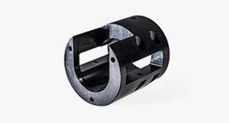
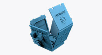
Let’s use this box and lid as a sheet metal tolerances case study. This will allow us to analyze the implications of sheet metal manufacturing on achievable tolerances. This assembly is deceiving in its simplicity. As we take a deep dive into the design, take a look at the nuances involved in designing good sheet metal parts.
First, take a look at the green lid. This part has four flanges formed up from the center section. This center section has four holes used to mount the lid to the pink box below it. These four holes are cut by a laser and their position and size is tightly controlled by a computer-controlled process. These holes will be located precisely and free from the impact of the surrounding bend angle and linear tolerances.

The situation is slightly different for the holes in our pink box. Unlike the holes on the lid, which are all on the same surface, the holes on the box are on four different surfaces each separated by four bends. Crossing the four bends, measuring hole-to-hole, gives us a linear tolerance of ±0.030 in. (±0.762mm) and a stacking angular tolerance of 1° per bend. This means the location of these holes is not nearly as tightly controlled as on the lid. It’s critical to keep this in mind when you are designing sheet metal components.
So, what can you do to overcome this? You could open the holes in the lid to allow for misalignment of mounting holes or use a floating hardware in the box which allows for misalignment between the lid and the box. Combine both approaches and you have effectively trivialized the stacking tolerances seen in the box. You end up with a functional assembly that mates reliably and will wow your customer with your sheet metal design prowess.
Tolerance Takeaways
We manufacture precision sheet metal components. However, precision is not the same across all manufacturing methods. A designer cannot expect to hold machining-like tolerances in their sheet metal part. If you understand this, and are thoughtful about design guidelines and your approach to sheet metal, you too can achieve great things with your parts.

If you have any issues getting your guide, click here to download.


Need custom sheet metal parts? Get an online quote today.
Upload a Part