

Hole Design for Fast, Cost-Effective Sheet Metal Parts
Deciphering the rules of the design for manufacturing road: what you need to know about hole-making in fabricated components
Hole-making is the most commonly performed of all sheet metal fabrication operations, but there’s also a lot to consider in design. With that, all companies must read the chapter on hole-making in their design for manufacturing (DFM) handbook before uploading a part.
Don’t have one of those handbooks lying around? That’s okay, neither does anyone else. The industry hasn’t yet produced a truly comprehensive best practices bible, which is why we produce design tips like this one to lead manufacturers down an often murky DFM path.
This design tip is all about hole-making in sheet metal parts. It will walk you through four of the most frequently encountered design advisories generated by our automated quoting software—think of them as helpful recommendations—and tells you how to solve these common issues. And as always, it will emphasize the fact that our applications engineering team stands ready to answer any nagging questions and assist with your next project.
Dealing with Incompatibility Issues
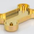
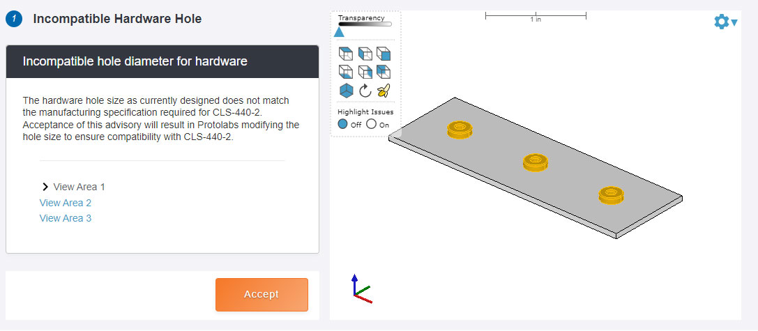
We offer MIG (metal inert gas) and TIG (tungsten inert gas) welding services, but as any designer knows, sometimes a less permanent joining method is desirable. And sometimes, fabricated parts need reinforcements or mounting hardware in certain areas. That’s where inserts, rivets, and threaded fasteners come in handy. However, each of these typically requires a mounting hole, and if you want those metal widgets to fit properly, it’s critical that the hole is sized correctly. Make a mistake here and you're likely to see this design advisory:
As you might expect, the text “hardware insert name” refers to one of the aforementioned fasteners, although it could also be a self-clinching nut, a flush-head stud, or any of the thousands of hardware items available through PEM and others. Whatever the components, accepting this design advisory only means that you're permitting Protolabs to make the hole larger or smaller as needed. No worries, the change will likely be minimal.
There's much more to the hardware discussion, including hole placement and material compatibility, so for additional information, we've devoted several pages to the topic in our downloadable (and free) guide, "Design Essentials for Sheet Metal Fabrication.”
Too Small, Too Thick
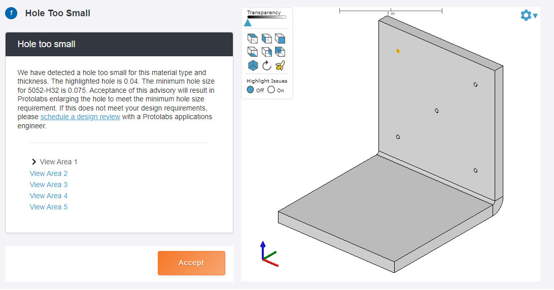
Sometimes, holes are the wrong size for reasons other than hardware. The following design advisory considers hole diameter relative to the material and available tooling. As a rule, it’s difficult to punch or laser-cut holes smaller in diameter than the material thickness, so calling for a 0.031 in. (0.787mm) hole in 11-gauge (0.119 in. or 3.0mm) mild steel is a non-starter, producing this message:
Unlike the previous hardware-related advisory, where hole size adjustments will probably be minor, this one could significantly affect part functionality. Read the message, take note of the minimum hole size, and accept or decline the change. And if the latter, please schedule some time to discuss it with one of our engineers. Chances are excellent that there's a solution.
Angling for Success
As noted earlier, sheet metal parts are often joined together with threaded fasteners, and in many cases, this is accomplished with—you guessed it—sheet metal screws. These have a threaded body that passes through the workpiece and an angled head that nestles into a countersunk hole, thus aligning the two components and allowing the head to sit flush. Sometimes though, a designer will specify a countersink angle that is incompatible with one of our standard 82°, 90°, 100°, or 120° fastener angles. The result is as follows:
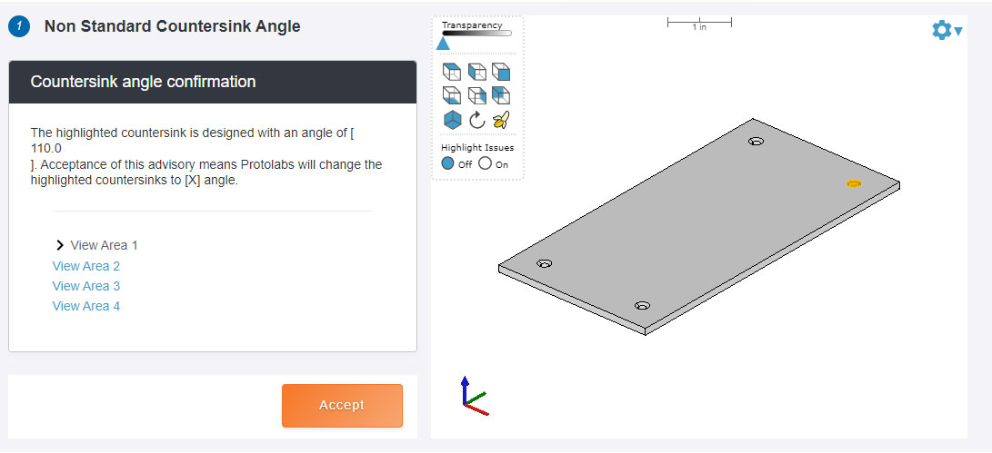
If there’s a specific reason for the countersink angle you specified, reject the design advisory and call our team to sort it out. If the angle was a simple oversight, accept the recommendation and move on. We’ll take it from here.
Counting on Countersinks
Similarly, countersink diameters can get overly large. Our standard tooling set accommodates major diameters (that’s the large end of the conical shape) between 0.090 in. (2.286mm) and 0.500 in. (12.7mm). Ask for one larger than this and you'll get this message:
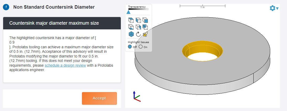
As with the “hole too small” message, there might be a perfectly valid reason for a supersized countersink diameter. No problem, call us and we’ll figure something out. Otherwise, click accept and get back to work. The same goes for design advisories that suggest the hardware insert is too close to an edge or a neighboring feature, counterbore-related alerts, material thickness errors, and so on.
For any design questions, give us a call at 877-479-3680 or send an email to [email protected] and we’ll give you a hand.

If you have any issues getting your guide, click here to download.