

How Much Does 3D Printing Cost? Key Factors to Consider.
Exploring the multiple ways you can lower your part costs at all stages when developing parts
What Factors Impact 3D Printing Cost?
No one wants to spend more money than necessary on parts development. Customers often think their choice of material has the biggest effect on cost, but while material does have some influence, the main cost drivers for additive parts are build time and finishing time. There are several design factors that affect build time, finishing time, or both. By factoring these considerations into your design, you can minimize the cost of your parts and improve overall part quality.

What is Build Time?
For all of Protolabs’ additive manufacturing technologies, build time is split into two categories: draw time and recoat time. Draw time is the time it takes to sinter, melt, or cure the material. It covers how long it takes for the laser to draw the cross section of each layer and is driven by the total volume of the build, including supports if applicable.
After the draw is done, the recoater blade travels across the build to distribute the next layer of raw material. The time it takes for the recoater blade to travel across the platform and back is typically a matter of seconds and will vary based on the size of the machine. The amount of recoat time is directly related to the height of the part in its optimal orientation. However, those seconds add up when you’re talking hundreds of layers-worth of recoat for every inch of build height.
If you were designing parts for machining, you would want to avoid removing material unless absolutely necessary because more cuts mean more cost. When designing for 3D printing, the mindset is the opposite; you only want to add material for the model if the material is critical, because more material means more cost.
Draw: Part Volume
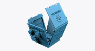
Part volume is a common factor that can drive the price up unnecessarily. The consideration should be your overall part volume and how much of that volume is critical to fit, form, or function. Below is a 5 in. x 2 in. x 3 in. (127mm x 50.8mm x 76.2mm) block where the critical features are channels. The ends of the part are also important because they help align the part in the assembly. This part is very high volume, but not all of that volume is critical to the function of the part. On the revised version, the channels are maintained as well as either end of the part. However, the rest of the material boxing in the channels has been removed, leaving about 0.1 in. of wall thickness for the channels. This reduces the part volume by 80% and can reduce the cost of the part by 50-60% depending on technology.

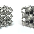
Another way to reduce material volume is to shell the part. This is best suited to selective laser sintering (SLS) and Multi Jet Fusion (MJF) since these do not require support structures. Additionally, since these processes see more heat than the other additive technologies, reducing volume will result in a higher quality part, because it avoids dimensional inaccuracies caused by material shrinkage. Below is an example of a 4 in. x 4 in. x 2 in. (101.6mm x 101.6mm x 50.8mm) organizer tray. The original model is very highvolume. The other two versions show different ways to reduce material.
The first method is to use ribs or honeycombs to maintain the structure and rigidity of the part, but also to remove any excess material. This method reduces the volume by 30% and reduces the cost by 20%.
If the rigidity of the part is less critical, you can hollow out the part instead. For this example part in the third column, hollowing reduces the volume by 36% and reduces the cost by 26%. Note that material should be reduced in a way that keeps the geometry open, to allow for complete removal of unsintered/unfused powder after the build. Sealed off cavities should be avoided.

Recoat: Part Orientation
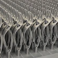
Recoat time is the second factor that drives build time and therefore cost. The recoat time is driven by the height of the build, but this isn’t necessarily based on the extents of the part. The build height is based on the height of the part in its optimal orientation. The optimal orientation will vary based on geometry, but generally, if the part can be designed to build in a shorter orientation it will be less expensive. You see this especially with stereolithography (SLA) and direct metal laser sintering (DMLS) since these technologies use support structure, which plays a significant role in choosing build orientation.
Here's a part that needs to be built in metal using DMLS. The first design iteration has channels that are too wide to build horizontally without requiring internal supports that will be trapped inside. However, changing the cross section of the channels to a self-supporting tear drop shape allows the part to build in the shorter, second orientation below. This small change reduces the cost by 18%.

Finishing Time and Strategies to Reduce It
When it comes to SLA and DMLS—the technologies requiring supports—finishing time is all about reducing the number of supports. This consideration goes hand-in-hand with build time because fewer supports means less time spent drawing, and later, removing them. Cutting down on finishing time is another way to shave off cost. Both technologies use supports that are made of the same material as the parts themselves.
For SLA, supports are removed easily; they can simply be plucked off by hand. After removing the supports, small braille-like bumps remain that get sanded down by our finishing team. Because support removal is relatively simple, having more of them doesn’t drive cost up as much when compared to metal supports with DMLS. However, if you’re looking at hundreds of parts, a few extra minutes of finishing time per part can add up.
On the other hand, supports on DMLS parts are more robust and can’t be removed by hand. These supports are cut off using rotary tools. For larger parts, we’ll even use a manual mill to help with the bulk removal of supports. Once the supports are cut off, the remaining burrs get ground and sanded down. Since the support removal process for DMLS is much more involved than SLA, reducing the number of supports will have the biggest effect on DMLS parts.

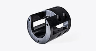
This 5 in. (127mm) tall pipe with flanges is a great example of a part that will have a large support volume because supports need to grow from the bottom flange all the way to the top flange to ensure it forms correctly. However, if the application for this part allows, it could be redesigned by reducing unnecessary material from the flange and adding some material so that the flanges grow in at a self-supporting 45-degree angle from the build plate.
Making this small change reduces the finishing time required from 3 hours per part to just 30 minutes and results in a 50% cost reduction! The image above shows both versions of the part, as well as the extent of supports that the first version requires versus the second version that was designed for additive manufacturing.

Final Thoughts
Additive manufacturing is a highly geometry-dependent process and strategies that work for one part or technology may not work for another part or technology. This article provides general guidelines on reducing cost and the examples featured were specifically created to demonstrate these guidelines. When it comes to applying these concepts, we’re more than happy to help. You can call our application engineering team at 877-479-3680 and we will discuss your specific project with you and provide part-specific suggestions for reducing cost.

If you have any issues getting your guide, click here to download.