

Understanding CNC Machining Tolerances
Maximize part quality, reduce cost, and navigate design challenges using standardized tolerances on machined parts
Eli Whitney, the inventor of the cotton gin, is credited with the concept of interchangeable parts. During a presentation to the United States Congress in 1801, he illustrated how all of the components needed for an assembly should be produced according to a set of exacting standards—to specific dimensions and tolerances, in other words—thus ensuring that the firing pin or gun barrel from one musket will fit into any other musket. His idea helped pave the way for the Second Industrial Revolution and what became known as the American System of Manufacturing.

The concepts of component interchangeability and dimensional tolerancing have since become an accepted part of manufacturing. Unfortunately, the misapplication of the latter can cause a host of problems. For instance, an overly stringent tolerance might require that parts go to a secondary grinding or EDM operation for completion, unnecessarily increasing costs and lead-time. Tolerances that are “too loose” or that aren’t in line with those of mating parts can make assembly impossible, leading to required rework, or in the worst case, making the finished product unusable.
To help avoid these unpleasant situations, this design tip includes some guidelines on how to properly apply part tolerances at Protolabs, along with a few definitions of the more commonly used callouts. We’ll also explore the industry standard for part tolerancing known as Geometric Dimensioning and Tolerancing (GD&T), a system defined under the American Society of Mechanical Engineers (ASME) Y14.5 specification.
Standardized Tolerances for CNC Machining
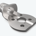
The standard prototype and production machining tolerance at Protolabs is +/- 0.005 in. (0.13mm). This means any part feature’s location, width, length, thickness, or diameter will not deviate by more than this amount from nominal. For example, the 1 in. (25.4mm)-wide bracket you're planning to order will measure between 0.995 and 1.005 in. (25.273 and 25.527mm) across, while the 0.25 in. (6.35mm) hole on one leg of that bracket will come in at 0.245 to 0.255 in. (6.223 to 6.477mm) diameter.
That’s pretty close, but if you need greater accuracy, there's our standard precision or production machining tolerance of +/-0.002 in. (0.051 mm). We're also able to hold +/- 0.0005 in. (0.0127mm) on reamed holes, and +/- 0.002 (0.051mm) on feature locations, provided those features are machined on the same side of the part. Depending on the part geometry and material, however, we can often achieve even greater accuracy, provided you make us aware of your requirements. For these and other exceptions, please be sure to note them on your part design when you upload the file(s) for quoting.

Tolerancing Guidelines for CNC Machining
Also, be aware that these are bilateral tolerances. If expressed in unilateral terms, the standard tolerance would read +0.000/- 0.010 in. (or +0.010/- 0.000 in.) while a limit-based tolerance in our bracket example would be 1.005 / 0.995 in.
All are acceptable, as are metric values, provided that you spell them out on the design. And to avoid confusion, please stick with the "three place" dimensions and tolerances shown, avoiding the extra zero in 1.0000 or 0.2500 in. unless there’s an overriding reason to do so.
Surface Roughness Considerations for Machining Tolerances
There’s more to part tolerancing than length, width, hole size, etc. There’s also surface roughness, which in the standard offering is equal to 63 µ in. for flat and perpendicular surfaces, and for curved surfaces, 125 µ in. or better.
This is an adequate finish for most uses, but for cosmetic surfaces on metal parts, we’re generally able to improve appearance through light bead blasting. Check out our CNC Surface Finish Guide for examples, and if you're in need of something smoother, note it on your design and we'll do our best to accommodate you.
Geometric Dimensioning and Tolerancing
Here’s another consideration. As mentioned earlier, we can accept GD&T tolerancing. This provides a deeper level of quality control that includes relationships between various part features as well as form and fit qualifiers. Below are a few of the more common ones:
- True position: In the bracket example cited earlier, we called out the hole location by specifying X and Y distances and their allowable deviation from a pair of perpendicular part edges. In GD&T, the hole’s location would be called out by its true position from a set of reference datums, accompanied by the qualifiers MMC (maximum material condition) or LMC (least material condition).
- Flatness: Milled surfaces are generally quite flat, but due to internal material stress or clamping forces during the machining process, some warpage can occur once the part has been removed from the machine, especially on thin-walled and plastic parts. A GD&T flatness tolerance controls this by defining two parallel planes within which a milled surface must lie.
- Cylindricity: For the same reasons that most milled surfaces are quite flat, most holes are quite round, as are turned surfaces. However, using a +/- 0.005 in. (0.127mm) tolerance, the 0.25 in. (6.35mm) hole in the bracket example could potentially be oblong, measuring 0.245 in. (6.223mm) one way and 0.255 in. (6.477mm) the other. Using cylindricity—defined as two concentric cylinders inside of which the machined hole must lie—manufacturers eliminate this unlikely situation.
- Concentricity: The rings on a bullseye are concentric, just as the wheels on your car are concentric to the axle. If a drilled or reamed hole must run perfectly true to a coaxial counterbore or circular boss, a concentricity callout is the best way to assure this.
- Perpendicularity: As its name implies, perpendicularity determines the maximum deviation of a horizontal machined surface to a nearby vertical surface. It can also be used to control the squareness of a turned shoulder to an adjacent diameter or the center axis of the part.
There are additional considerations to GD&T, including parallelism, straightness, profile, and angularity, all of which are spelled out in ASME Y14.5. As with any other non-standard tolerances, however, they must be called out on the design at the time of upload. Tolerancing with GD&T also means that projects will bypass our automated Protolabs quoting process and be rerouted to our myRapid quoting experience for our CNC machining high-precision/high-quantity option.

Why High-precision/High-quantity Machining?
So, what is the difference between our machining options? For starters, a quote for high-precision/high-quantity machining is not automated as it is with our automated machining option, so the quote might take a day for human review. With high-precision machining, the finished part lead-time is also a little longer, with seven to 10 days as standard. We require a 3D CAD model, along with a 2D drawing for GD&T tolerances. It could also mean that we go beyond our standard cutting tool set and use machining processes such as wire EDM, EDM hole popping, grinding, and boring to meet your part quality requirements.
Another option that should be mentioned in this context is quality control and documentation. Upon request, we’ll measure parts on one of our CMMs (coordinate measuring machine) and other metrology equipment. We will also work with you on the Production Part Approval Process (PPAP), provide a Certificate of Conformance (CoC) to your specifications, and provide First Article Inspections (FAIs), material certifications, and heat lot numbers.
Ultimately, we’re here to support your project from prototyping to production, whatever the tolerance requirements. This is because we offer both a fully automated machining option for fast turnaround or a high-precision option with extended milling and post-machining capabilities for the highest complexity parts. We have all of your CNC milling and turning needs covered. Just give us a call or send an email if you want to know more. We always have applications engineers available to assist with any questions at [email protected] or 877-479-3680. Ready to start your next project? Just upload a CAD file to our website.