Guideline für das Gewindeschneiden


|
Gewindeteil in 5 einfachen Schritten:
|
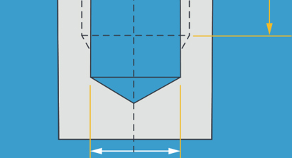
Die Gewindetiefe verstehen: Alle unsere Gewinde werden mit einer Gewindeschneidmaschine CNC-gefräst und bei der Endkontrolle manuell geeicht. Das Gewindefräsen ist zuverlässiger als das manuelle Gewindeschneiden, für bessere Ergebnisse wird die Gewindetiefe auf etwa das 2,5-fache des Gewindedurchmessers eingestellt (siehe maximale Tiefe in der Tabelle unten). Es ist kein Problem, wenn Ihr Loch länger oder kürzer ist, denn unsere Software entwirft Ihr Gewinde wie folgt: |
SCHNELLDREHEN |
|
Sackloch <Ø×2.5Gewinde bis zum Ende (der letzte Gewindegang endet etwa 0,25 mm vor dem Lochende oder der Bohrspitze) |
 |
Sackloch >Ø×2,5Der erste Abschnitt des Lochs wird mit einem Gewinde versehen (bis zu einer Tiefe von ca. Ø×2,5 oder siehe MAXIMALE GEWINDETIEFE in der untenstehenden Tabelle). |
 |
Durchgangsloch <Ø×2,5Durchgehendes Gewinde. |
 |
Durchgangsloch >Ø×2,5Wenn wir zu beiden Seiten Zugang haben, können eine oder beide Seiten für das Gewinde ausgewählt werden. Wenn Sie beide Seiten auswählen, betragen die Gewinde jeweils etwas weniger als die halbe Lochtiefe. Sie treffen sich nicht in der Mitte. Alternativ wird das Gewinde auf die maximale Tiefe der gewählten Seite geschnitten (etwa Ø×2,5). |
 |
Durchgangsloch >Ø×5Bei längeren Löchern werden die Gewinde zur maximal möglichen Tiefe geschnitten (etwa Ø×2,5). |
 |
Tipp für eine größere GesamttiefeDurch Hinzufügen einer Senkung reicht das Gewindewerkzeug weiter. Eine Senkung ist auch ein nützliches Merkmal beim montageorientierten Entwerfen (DfA – Design for Assembly). |
 |
Drahtgewindeeinsätze und Einsätze mit Sperrkeilen
Drahtgewindeeinsätze (HELICOIL®) und Einsätze mit Sperrkeilen können in weicheren Materialien für robustere Gewinde sorgen. Wir können einsatzbereite Gewinde bearbeiten. Diese können Sie mit unserem interaktiven Angebot auswählen.
Wir liefern und montieren auch eine Reihe von metrischen HELICOIL® Standardeinsätzen mit einer Gewindelänge von 1 × Gewindedurchmesser (D), 1,5D und 2D. Wenn Sie montierte Einsätze benötigen, teilen Sie uns dies bitte über die Schaltfläche "Spezielle Anweisungen" in Ihrem Angebot mit; geben Sie dabei bitte die Einsatzlänge und die Position an.
Weitere Überlegungen:
Es kann vorkommen, das Teilemerkmale oder Aufspannvorrichtungen die Gewindewerkzeuge behindern. Wenn ein Loch nicht mit einem Gewinde versehen werden kann, zeigen wir dies, indem wir das Gewinde im interaktiven Angebot weglassen.
Bei Gewinden für Drehteile modellieren Sie einfach den Nenndurchmesser, das Gewinde selbst brauchen Sie nicht zu entwerfen.
Unser standardisierter Werkzeugsatz ermöglicht außerordentlich schnelle CNC-Fertigung (manchmal schon am gleichen Tag). Das bedeutet jedoch auch, dass wir nur die gelisteten Gewinde anbieten. Linksgewinde und nicht aufgeführte Durchmesser oder Steigungen können wir derzeit nicht liefern.
Wir unterstützen nur modellierte Gewinde ab M12 oder UNC ½”-13 (½” Zoll vereinheitlicht grob mit 13 TPI). Diese werden mit einem Kugelfräser gefertigt.
Dateien im SLT-Format werden nicht unterstützt.
Was ist die Mindestgewindetiefe? Unsere Software erkennt Löcher, die mit einem Gewinde versehen werden können und eine Tiefe von mindestens 1,5 x Gewindesteigung haben.
Wie berechnet sich die empfohlene Mindestgewindetiefe? Die empfohlene Mindesttiefe für ein starkes Gewinde beträgt 1 x Durchmesser bei Stahl und harten Metallen, 2 x Durchmesser bei Aluminiumlegierungen und weichen Metallen und so tief wie möglich bei Kunststoffen: 2,5 x Ø (die Verwendung eines Helicoil® -Einsatzes wird empfohlen, um die Gewindestärke und Haltbarkeit bei weichen Materialien zu erhöhen).
Metrisches Innengewinde
| Metrisches Gewinde
|
Prozess | Maximale Gewindetiefe | CAD Ø * | Durchmesser der im Modell dargestellten Bohrung | Min. geforderte Freibohrung Ø | ||
|---|---|---|---|---|---|---|---|
| FRÄSEN | DREHEN | MIN | MAX | ||||
|
Metrisches Innengewinde: standard oder grob - alle Maße in mm |
|||||||
| M1.6 x 0.35** | Weich** | 3.00 | 1.25 | 1.22 | 1.32 | 1.65 | |
|
M2 x0.4 |
✓ | 5.08 | 1.60 | 1.57 | 1.68 | 2.05 | |
|
M2.5 x 0.45 |
✓ | 5.08 | 2.05 | 2.01 | 2.14 | 2.60 | |
|
M3 x 0.5 |
✓ | ✓ | 7.62 | 2.50 | 2.46 | 2.60 | 3.10 |
|
M3.5 x 0.6 |
✓ | ✓ | 10.16 | 2.90 | 2.85 | 3.01 | 3.60 |
|
M4 x 0.7 |
✓ | ✓ | 10.16 | 3.30 | 3.24 | 3.42 | 4.10 |
|
M5 x 0.8 |
✓ | ✓ | 15.24 / 10.16T* | 4.20 | 4.14 | 4.33 | 5.10 |
|
M6 x 1.0 |
✓ | nur axial | 16.51 / 12.27T* | 5.00 | 4.92 | 5.15 | 6.10 |
|
M8 x 1.25 |
✓ | nur axial | 16.51 / 12.27T* | 6.80 | 6.65 | 6.91 | 8.20 |
|
M10 x 1.5 |
✓ | 25.40 | 8.50 | 8.38 | 8.68 | 10.20 | |
|
M12 x 1.75 |
✓ | 25.40 | 10.20 | 10.00 | 10.44 | 12.20 | |
|
Metrisches Innengewinde: fein oder spezial - alle Maße in mm |
|||||||
|
M8 x 1.0 FINE |
Metall*** | nur axial | 16.51 | 7.00 | 6.91 | 7.16 | 8.20 |
|
M10 x 1.25 FINE |
Metall*** | nur axial | 25.40 | 8.75 | 8.65 | 8.91 | 10.20 |
|
M12 x 1.25 FINE |
Metall*** | 25.40 | 10.75 | 10.65 | 10.91 | 12.20 | |
Blockierung durch andere Merkmale Ihres Teils, Einführungsbearbeitungen oder Aufspannvorrichtungen können die maximale Tiefe von Gewinden reduzieren.
* auch als Kernlochbohrer-Ø bezeichnet
Weich** - nur aus weichen Metallen verfügbar
Metall *** - nur aus Metallwerkstoffen verfügbar (hart und weich)
T* - gedreht
Mindest- und Höchstdurchmesser sind die Grenzwerte für die Erkennung von für Gewinde geeigneten Löchern durch unsere Software.
Die maximale Gewindetiefe ist der Grenzwert für unsere Gewindeschneidewerkzeuge. Sie wird von der für das Loch ausgewählten Fläche aus gemessen und schließt Fasen oder Senkungen aus. Das Loch muss wegen der anfallenden Späne tiefer sein als dieses Maß. Auch wenn das Design ein tieferes Loch aufweist, wird nur der erste Abschnitt mit einem Gewinde versehen.
Metrische Drahteinsätze
Drahteinsätze sind nicht im Lieferumfang enthalten.
Wir können Helicoils für alle mit # gekennzeichneten Gewinde liefern und montieren. Bitte fragen Sie diese bei der Angebotsanfrage über das Eingabefeld für spezielle Anweisungen an.
| Metrische Gewinde
|
Prozess | Maximale Gewindetiefe | CAD Ø * | Durchmesser der im Modell dargestellten Bohrung | Min. geforderte Freibohrung Ø | ||
|---|---|---|---|---|---|---|---|
| FRÄSEN | DREHEN | MIN | MAX | ||||
|
Metrisches Innengewinde: standard oder grob - alle Maße in mm |
|||||||
| M2 x 0.4 | ✓# | 5.08 | 2.14 | 2.09 | 2.14 | 2.05 | |
| M2.5 x 0.45 | ✓# | ✓# | 7.62 | 2.6 | 2.55 | 2.65 | 2.60 |
| M3 x 0.5 | ✓# | ✓# | 10.16 | 3.18 | 3.11 | 3.25 | 3.10 |
| M3.5 x 0.6 | ✓ | ✓ | 15.24 / 10.16T* | 3.7 | 3.68 | 3.79 | 3.60 |
| M4 x 0.7 | ✓# | ✓# | 15.24 / 10.16T* | 4.24 | 4.15 | 4.33 | 4.10 |
| M5 x 0.8 | ✓# | ✓# | 16.51 / 10.16T* | 5.27 | 5.17 | 5.37 | 5.10 |
| M6 x 1.0 | ✓# | nur axial # | 16.51 / 12.7T* | 6.31 | 6.22 | 6.41 | 6.10 |
| M8 x 1.25 | ✓# | nur axial # | 25.4 / 12.7T* | 8.38 | 8.27 | 8.48 | 8.20 |
| M10 x 1.5 | ✓# | 30.48 | 10.56 | 10.33 | 10.56 | 10.20 | |
| M12 x 1.75 | ✓# | 30.48 | 12.51 | 12.38 | 12.64 | 12.20 | |
* auch als Kernlochbohrer-Ø bezeichnet
T* - gedreht
✓ = Gewinde sind verfügbar: Außendurchmesser (auf Achse), Innendurchmesser: auf Achse, axial und radial.
# = Helicoil® Gewindeeinsätze können auf Anfrage eingebaut werden und sind mit einer Gewindelänge von 1 × Gewinde-Nenndurchmesser (D), 1,5D und 2D erhältlich.
Metrisches Außengewinde
| Metrische Gewinde
|
Prozess | Maximale Gewindetiefe | CAD Ø * | Durchmesser der Modell dargestellten Bohrung | Min. geforderte Freibohrung Ø | ||
|---|---|---|---|---|---|---|---|
| FRÄSEN | DREHEN | MIN | MAX | ||||
|
Metrisches Außengewinde: standard oder grob - alle Maße in mm |
|||||||
|
M3.5 x 0.6 |
✓ | 7 | 3.5 | 3.35 | 3.53 | 3.16 | |
|
M4 x 0.7 |
✓ | 8 | 4 | 3.84 | 4.03 | 4.10 | |
|
M5 x 0.8 |
✓ | 10 | 5 | 4.83 | 5.03 | 5.10 | |
|
M6 x 1.0 |
✓ | 12 | 6 | 5.79 | 6.02 | 6.10 | |
|
M8 x 1.25 |
✓ | 16 | 8 | 7.76 | 8.03 | 8.20 | |
|
M10 x 1.5 |
✓ | 20 | 10 | 9.73 | 10.03 | 10.20 | |
|
M12 x 1.75 |
M* | ✓ | 24 | 12 | 11.7 | 12.02 | 12.20 |
|
M14 x 2.0 |
M* | ✓ | 28 | 14 | 13.68 | 14.03 | 14.25 |
|
M16 x 2.0 |
M* | ✓ | 32 | 16 | 15.68 | 16.02 | 16.25 |
|
M20 x 2.5 |
M* | ✓ | 40 | 20 | 19.62 | 20.03 | 20.25 |
|
Metrischer Außendurchmesser: fein oder speziell - alle Maße in mm |
|||||||
|
M8 x 1.0 FINE |
✓ | 16 | 8 | 7.8 | 8.03 | 8.20 | |
|
M10 x 0.75 SP |
✓ | 20 | 10 | 9.84 | 10.03 | 10.20 | |
|
M10 x 1.25 FINE |
✓ | 20 | 10 | 9.76 | 10.03 | 10.20 | |
|
M12 x 1.25 FINE |
✓ | 24 | 12 | 11.76 | 12.02 | 12.20 | |
|
M12 x 1.0 SP |
✓ | 24 | 12 | 11.79 | 12.02 | 12.20 | |
|
M12 x 1.5 SP |
M* | ✓ | 24 | 12 | 11.73 | 12.02 | 12.20 |
|
M14 x 1.5 FINE |
M* | ✓ | 28 | 14 | 13.73 | 14.03 | 14.25 |
|
M15 x 1.0 SP |
M* | ✓ | 30 | 15 | 14.79 | 15.03 | 15.25 |
|
M16 x 1.5 FINE |
M* | ✓ | 32 | 16 | 15.73 | 16.02 | 16.25 |
|
M17 x 1.0 SP |
M* | ✓ | 34 | 17 | 16.79 | 17.03 | 17.25 |
|
M18 x 1.5 FINE |
M* | ✓ | 36 | 18 | 17.73 | 18.03 | 18.25 |
|
M20 x 1.5 FINE |
M* | ✓ | 40 | 20 | 19.73 | 20.03 | 20.25 |
* auch als Kernlochbohrer-Ø bezeichnet
M* Auf einer 3- oder 5-Achs-Fräsmaschine können größere externe Gewinde mit einem Kugelfräser geschnitten werden – siehe „Spezielle Gewinde“.
Innengewinde (Zoll)
| Gewinde
|
Prozess | Maximale Gewindetiefe | CAD Ø * | Durchmesser der im Modell dargestellten Bohrung | Min. geforderte Freibohrung Ø | ||
|---|---|---|---|---|---|---|---|
| FÄSEN | DREHEN | MIN | MAX | ||||
|
Innengewinde: Einheits-Feingewinde (UNF) - alle Abmessungen in Zoll |
|||||||
| #2-64 | ✓ | 0.20 | 0.072 | 0.069 | 0.075 | 0.09 | |
| #3-56 | ✓ | 0.20 | 0.083 | 0.080 | 0.084 | 0.10 | |
| #4-48 | ✓ | ✓ | 0.30 | 0.093 | 0.087 | 0.099 | 0.12 |
| #5-44 | ✓ | ✓ | 0.30 | 0.104 | 0.100 | 0.104 | 0.13 |
| #6-40 | ✓ | ✓ | 0.40 | 0.115 | 0.111 | 0.119 | 0.14 |
| #8-36 | ✓ | ✓ | 0.40 | 0.138 | 0.134 | 0.142 | 0.17 |
| #10-32 | ✓ | ✓ | 0.60 | 0.160 | 0.156 | 0.164 | 0.19 |
| #12-28 | ✓ | nur axial | 0.6 / 0.5T* | 0.182 | 0.177 | 0.186 | 0.22 |
| 1/4-28 | ✓ | nur axial | 0.65 | 0.216 | 0.211 | 0.220 | 0.26 |
| 5/16-24 | ✓ | nur axial | 0.65 /0.5T* | 0.272 | 0.267 | 0.277 | 0.32 |
| 3/8-24 | ✓ | nur axial | 1 / 0.5T* | 0.335 | 0.330 | 0.340 | 0.38 |
| 7/16-20 | ✓ | nur axial | 1 / 0.5T* | 0.389 | 0.383 | 0.395 | 0.44 |
| 1/2-20 | ✓ | nur axial | 1.2 / 0.5T* | 0.452 | 0.446 | 0.457 | 0.51 |
|
Innengewinde: Einheits-Grobgewinde (UNC) - alle Maße in Zoll |
|||||||
| #2-56 | ✓ | 0.20 | 0.070 | 0.067 | 0.074 | 0.09 | |
| #3-48 | ✓ | 0.20 | 0.082 | 0.076 | 0.084 | 0.10 | |
| #4-40 | ✓ | ✓ | 0.30 | 0.089 | 0.085 | 0.094 | 0.12 |
| #5-40 | ✓ | ✓ | 0.30 | 0.102 | 0.098 | 0.104 | 0.13 |
| #6-32 | ✓ | ✓ | 0.40 | 0.109 | 0.105 | 0.114 | 0.14 |
| #8-32 | ✓ | ✓ | 0.40 | 0.135 | 0.130 | 0.139 | 0.17 |
| #10-24 | ✓ | 0.60 | 0.151 | 0.145 | 0.156 | 0.19 | |
| #12-24 | ✓ | nur axial | 0.6 / 0.5T* | 0.176 | 0.171 | 0.181 | 0.22 |
| 1/4-20 | ✓ | nur axial | 0.65 / 0.5T* | 0.202 | 0.196 | 0.207 | 0.26 |
| 5/16-18 | ✓ | 0.65 | 0.259 | 0.252 | 0.265 | 0.32 | |
| 3/8-16 | ✓ | 1.00 | 0.314 | 0.307 | 0.321 | 0.38 | |
| 7/16-14 | ✓ | 1.00 | 0.372 | 0.360 | 0.376 | 0.44 | |
| 1/2-13 | ✓ | 1.00 | 0.426 | 0.417 | 0.434 | 0.51 | |
* auch als Kernlochbohrer-Ø bezeichnet
T* - gedreht
Drahteinsätze (Zoll)
Drahteinsätze in Zolleinheit werden von uns nicht angeboten.
| Gewinde
|
Prozess | Maximale Gewindetiefe | CAD Ø * | Durchmesser der im Modell dargestellten Bohrung | Min. geforderte Freibohrung Ø | ||
|---|---|---|---|---|---|---|---|
| FRÄSEN | DREHEN | MIN | MAX | ||||
|
Drahteinsätze: Einheits-Feingewinde (UNF)- alle Maße in Zoll |
|||||||
|
#2-64 |
✓ | ✓ | 0.30 | 0.093 | 0.089 | 0.095 | N/A |
|
#3-56 |
✓ | ✓ | 0.30 | 0.104 | 0.102 | 0.104 | N/A |
|
#4-48 |
✓ | ✓ | 0.40 | 0.120 | 0.116 | 0.123 | N/A |
|
#6-40 |
✓ | ✓ | 0.60 | 0.147 | 0.144 | 0.150 | N/A |
|
#8-36 |
✓ | ✓ | 0.60 | 0.173 | 0.170 | 0.177 | N/A |
|
#10-32 |
✓ | ✓ | 0.65 | 0.201 | 0.196 | 0.204 | N/A |
|
1/4-28 |
✓ | nur axial | 0.65 | 0.261 | 0.257 | 0.265 | N/A |
|
5/16-24 |
✓ | nur axial | 1.00 | 0.325 | 0.321 | 0.329 | N/A |
|
3/8-24 |
✓ | nur axial | 1.00 | 0.388 | 0.384 | 0.391 | N/A |
|
#7/16-20 |
✓ | nur axial | 1.00 | 0.452 | 0.448 | 0.456 | N/A |
|
1/2-13 |
✓ | nur axial | 1.00 | 0.426 | 0.417 | 0.434 | N/A |
|
Drahteinsätze: Einheits-Grobgewinde (UNC) - alle Maße in Zoll |
|||||||
|
#2-56 |
✓ | ✓ | 0.30 | 0.091 | 0.090 | 0.096 | N/A |
|
#3-48 |
✓ | ✓ | 0.40 | 0.107 | 0.105 | 0.110 | N/A |
|
#4-40 |
✓ | ✓ | 0.40 | 0.119 | 0.117 | 0.125 | N/A |
|
#5-40 |
✓ | ✓ | 0.40 | 0.132 |
0.131 |
0.137 | N/A |
|
#6-32 |
✓ | ✓ | 0.60 | 0.147 | 0.145 | 0.153 | N/A |
|
#8-32 |
✓ | ✓ | 0.60 | 0.173 | 0.171 | 0.178 | N/A |
|
#10-24 |
✓ | nur axial | 0.65 | 0.201 | 0.199 | 0.208 | N/A |
|
#12-24 |
✓ | nur axial | 0.65 | 0.227 | 0.225 | 0.234 | N/A |
|
1/4-20 |
✓ | nur axial | 0.65 | 0.266 | 0.261 | 0.270 | N/A |
|
5/16-18 |
✓ | 1.00 | 0.332 | 0.324 | 0.334 | N/A | |
|
3/8-16 |
✓ | 1.20 | 0.397 | 0.389 | 0.399 | N/A | |
|
7/16-14 |
✓ | 1.20 | 0.453 | 0.453 | 0.464 | N/A | |
|
1/2-13 |
✓ | 1.20 | 0.531 | 0.515 | 0.531 | N/A | |
* auch als Kernlochbohrer-Ø bezeichnet
Gewindeeinsätze (Zoll)
Gewindeeinsätze in Zolleinheit werden von uns nicht angeboten.
| Gewinde
|
Prozess | Maximale Gewindetiefe | CAD Ø * | Durchmesser der im Modell dargestellten Bohrung | Min. geforderte Freibohrung Ø | ||
|---|---|---|---|---|---|---|---|
| FRÄSEN | DREHEN | MIN | MAX | ||||
| Gewindeeinsätze: Einheits-Feingewinde (UNF) - alle Maße in Zoll | |||||||
|
#10-32 |
✓ | 0.600 | 0.162 | 0.160 | 0.164 | N/A | |
|
#12-28 |
✓ | 0.600 | 0.189 | 0.186 | 0.191 | N/A | |
|
1/4-28 |
✓ | 0.650 | 0.229 | 0.227 | 0.231 | N/A | |
|
Gewindeeinsätze: Einheits-Grobgewinde (UNC) - alle Maße in Zoll |
|||||||
|
#8-32 |
✓ | 0.400 | 0.135 | 0.133 | 0.137 | N/A | |
|
5/16-18 |
✓ | 0.650 | 0.274 | 0.271 | 0.276 | N/A | |
|
3/8-16 |
✓ | 1.000 | 0.334 | 0.331 | 0.336 | N/A | |
|
7/16-14 |
✓ | 1.000 | 0.399 | 0.396 | 0.401 | N/A | |
|
1/2-13 |
✓ | 1.000 | 0.455 | 0.452 | 0.457 | N/A | |
* auch als Kernlochbohrer-Ø bezeichnet
Außengewinde (Zoll)
| Gewinde
|
Prozess | Maximale Gewindetiefe | CAD Ø * | Durchmesser der im Modell dargestellten Bohrung | Min. geforderte Freibohrung Ø | ||
|---|---|---|---|---|---|---|---|
| FRÄSEN | DREHEN | MIN | MAX | ||||
|
Außengewinde: Einheits-Feingewinde (UNF) - alle Maße in Zoll |
|||||||
|
#5-44 |
✓ | 0.250 | 0.125 | 0.12 | 0.126 | 0.13 | |
|
#6-40 |
✓ | 0.280 | 0.138 | 0.132 | 0.139 | 0.14 | |
|
#8-36 |
✓ | 0.330 | 0.164 | 0.158 | 0.165 | 0.17 | |
|
#10-32 |
✓ | 0.380 | 0.190 | 0.183 | 0.191 | 0.19 | |
|
#12-28 |
✓ | 0.430 | 0.216 | 0.209 | 0.217 | 0.22 | |
|
1/4-28 |
✓ | 0.500 | 0.250 | 0.243 | 0.251 | 0.26 | |
|
5/16-24 |
✓ | 0.630 | 0.313 | 0.304 | 0.314 | 0.32 | |
|
3/8-24 |
✓ | 0.750 | 0.375 | 0.367 | 0.376 | 0.38 | |
|
7/16-20 |
✓ | 0.880 | 0.438 | 0.428 | 0.439 | 0.44 | |
|
1/2-20 |
M* | ✓ | 1.000 | 0.500 | 0.491 | 0.501 | 0.51 |
|
5/8-18 |
M* | ✓ | 1.250 | 0.625 | 0.615 | 0.626 | 0.64 |
|
3/4-16 |
M* | ✓ | 1.500 | 0.750 | 0.739 | 0.751 | 0.76 |
|
Außengewinde: Einheits-Grobgewinde (UNC) - alle Maße in Zoll |
|||||||
|
#4-40 |
✓ | 0.22 | 0.112 | 0.106 | 0.113 | 0.12 | |
|
#5-40 |
✓ | 0.25 | 0.125 | 0.119 | 0.126 | 0.13 | |
|
#6-32 |
✓ | 0.28 | 0.138 | 0.131 | 0.139 | 0.14 | |
|
#8-32 |
✓ | 0.33 | 0.164 | 0.157 | 0.165 | 0.17 | |
|
#10-24 |
✓ | 0.38 | 0.190 | 0.182 | 0.191 | 0.19 | |
|
#12-24 |
✓ | 0.43 | 0.216 | 0.208 | 0.217 | 0.22 | |
|
1/4-20 |
✓ | 0.50 | 0.250 | 0.241 | 0.251 | 0.26 | |
|
5/16-18 |
✓ | 0.63 | 0.313 | 0.303 | 0.314 | 0.32 | |
|
3/8-16 |
✓ | 0.75 | 0.375 | 0.364 | 0.376 | 0.38 | |
|
7/16-14 |
✓ | 0.88 | 0.438 | 0.426 | 0.439 | 0.44 | |
|
1/2-13 |
M* | ✓ | 1.00 | 0.500 | 0.488 | 0.501 | 0.51 |
|
5/8-11 |
M* | ✓ | 1.25 | 0.625 | 0.611 | 0.626 | 0.64 |
|
3/4-10 |
M* | ✓ | 1.50 | 0.750 | 0.735 | 0.751 | 0.76 |
* auch als Kernlochbohrer-Ø bezeichnet
M* Auf einer 3- oder 5-achsigen indexierten Fräsmaschine können größere Außengewinde mit einem Kugelkopffräser geschnitten werden, siehe "spezielle Außengewinde".
Spezielle Außengewinde
Außengewinde können gefräst werden, was normalerweise nur bei größeren Gewinden gut funktioniert, da diese mit einem Kugelfräser gefräst werden (M4 ist das absolute Minimum, ideal sind M12 und größer). Ihr Gewinde hat Radien im Gewindegrund und muss daher eventuell mit einem Schneideisen gereinigt werden. Wir können die meisten kundenspezifischen Gewinde oder schraubenförmigen Formen fräsen, die Sie modellieren können - auf der Drehmaschine, der 5-Achsen-Indexfräsmaschine oder der 3-Achsen-Fräsmaschine.
Bei Teilen, die ein gefrästes Außengewinde benötigen, müssen Sie die Gewinde bei Ihrem Teiledesign entwerfen. Wir setzen Ihren Entwurf mithilfe von Schaft- und Kugelfräsern um. Dies ist zwar nicht die bevorzugte Methode für die Herstellung von Gewinden, sie kann sich bei der Herstellung von Vierteldrehverschlüssen oder spiralförmigen und mithilfe einer Nocke hergestellte Merkmalen als hilfreich erweisen.
Die CAD-Datei sollte anschließend in einem anderen Dateiformat als STL vorgelegt werden. Wir akzeptieren die meisten nativen CAD-Formate bzw. Standard-Dateiformate, wie IGES oder STEP.
Hinweis: Wählen Sie bei Standardgewinden bitte nur den Bohrertyp oder den Außendurchmesser aus, da wir keine modellierten Standardgewinde herstellen können.