


3 Gate Considerations to Improve Mouldability
Examine gate type and location when designing parts for injection moulding
Let’s face it: a gate is a necessary evil, a break in the otherwise continuous surface of an injection mould. While its vestiges are typically removed after moulding, either automatically or manually, it leaves its “footprint” on the finished part. Without it there would be no part, so since we can’t do away with gates and because they can impact both the mouldability and quality of the part, there is good reason to consider their type and location in designing parts. Of course, even if you don’t think about gates when designing your part, you will have a chance to approve their type and location when you confirm your Protolabs order.
At Protolabs, we use tab, hot tip, or pin gates depending on the shape and size of the part and the resin being injected.

Tab Gates
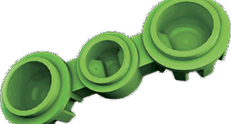
The tab gate is the most commonly used of the three types. It consists of a trapezoidal block milled into the parting line on an exterior surface of the part (see Figure 1), and is usually placed in a thicker wall section rather than thinner areas. Its position usually makes it easy to trim off, and while it typically leaves the largest vestige of the three gate types, its position at the parting line affects only the edge of the part, where it usually does not interfere with function or cosmetics.
The tab gate is easy to manufacture, maintain, and process, and there is typically a great deal of latitude in its placement along the parting line. Its design helps confine stress generated during ejection to the tab, which is trimmed off after moulding. Also, being relatively large, it is ideal for use with filled resins, which can be difficult to inject through smaller gates. For all these reasons the tab gate is the first choice among gates.

Hot Tip Gates
The hot tip gate is positioned near the centre of a part rather than at the edge. This reduces the distance resin must travel to fill the mould and helps centre the clamping force the press applies to the mould. Figure 2 shows an image from a sample Protolabs order confirmation with a hot tip gate location. The yellow cylinder is a cavity milled into the A-side mould half to which a single-drop hot tip will be bolted. Hot tip gates are always on the A-side.
The hot tip gate is often used on round or domed parts to achieve radial flow rather than the linear flow of a tab gate. Also, because this gate takes up no space at the edge of the mould cavity, it can be used on parts approaching Protomold’s maximum part footprint size. The gate leaves a small raised bump, typically 1.5mm to 2mm in diameter and 0.3mm to 0.5mm high, that can be trimmed flush to 0.13mm proud. Depending on part geometry and resin type, a hot tip gate can also leave “blush” or flow marks in a circular pattern around the gate site. These can be problematic because they are typically on the cosmetic surface of the part. Another problem is the potential for degrading resin in small shot sizes. And finally, because it is a small gate, a hot tip can become plugged if used to inject resins with high glass fill content.

Pin Gates
The pin gate is the least common of the three gates. It is typically used for complex parts that cannot have gate vestiges on the edges where tab gates would be or on the cosmetic side of the part where hot tip gates are located. It is the only one of the three gate-types that is located on the B-side of the mould, typically the non-cosmetic surface.
Instead of introducing resin into the mould cavity where the part is formed, a pin gate injects resin into the ejector pin channel (see Figure 3). The ejector pin, shown in yellow below, is shortened, and resin is injected from the cone-shaped “tunnel” gate through the empty section of the ejector pin channel, shown in purple, and into the mould to form the part. Once the resin has hardened, the ejector pin pushes against the cylindrical post in the pin channel to eject the part from the B-side mould half. The ejector pin shears the post from the tunnel gate, leaving the post rising from the surface of the ejected part. The post is later removed in a manual process. Because it injects resin through an ejector pin hole, this gate creates a vestige on the finished part like an ejector pin but trimmed flush to 0.13mm proud instead of the standard ejector pin that is flush to 0.13mm recessed into the part
The use of the pin gate is very geometry-dependent, and while it can produce excellent results, it can be challenging to process. The cone-shaped tunnel gate precludes the use of many glass-filled resins, and the shearing of the cone from the post during ejection can place significant stress on the mould. Finally, the angle and depth of the cone rules out its use with many geometries, such as housings or other cored-out parts.
Clearly, gating can involve complex choices, but Protolabs will select the gate type and position that seems best suited to your design and resin. You, in turn, will have the opportunity to review the gate placement on your order confirmation. If you have questions or concerns, you can contact our Application Engineers at +44 (0) 1952 683047 to discuss options.