


DMLS - Direct Metal Laser Sintering
Your masterclass in product design and development
Protolabs’ Insight video series
Our Insight video series will help you master digital manufacturing.
Every Friday we’ll post a new video – each one giving you a deeper Insight into how to design better parts. We’ll cover specific topics such as choosing the right 3D printing material, optimising your design for CNC machining, surface finishes for moulded parts, and much more besides.
So join us and don’t miss out.
Insight: DMLS - Direct Metal Laser Sintering
Transcript
Hello and welcome to this week’s Insight.
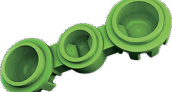
Today we’re looking at a particular production process, and the ways it can help you and your business. Specifically, an industrial 3D printing process known as direct metal laser sintering, or DMLS for short.
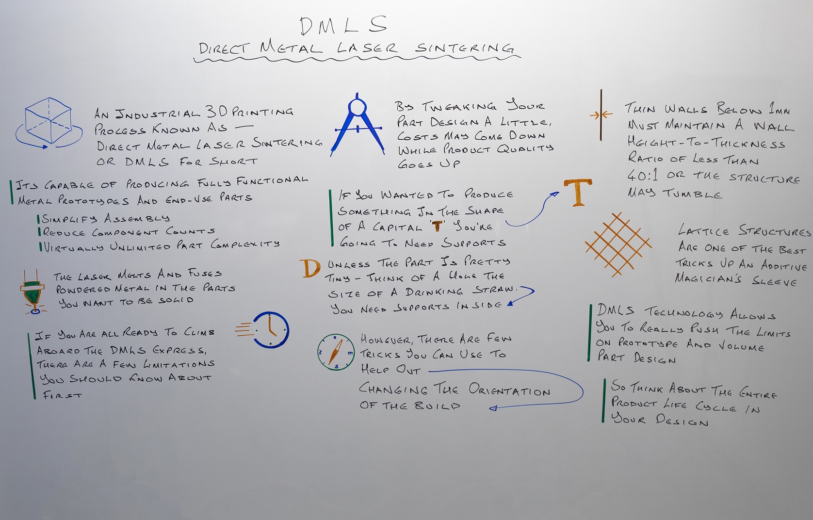
This is one of the most revolutionary and – if I’m being honest – coolest pieces of additive manufacturing out there. It’s capable of producing fully functional metal prototypes and end-use parts; it can simplify assembly by reducing component counts; and it offers virtually unlimited part complexity with no additional cost.

The basic concept behind it is actually surprisingly simple. It works by taking a model and dividing it up into paper-thin layers and then, well, the best term is probably “drawing” those layers into a bed of powdered metal with a laser. The laser melts and fuses the powdered metal in the parts you want to be solid. Repeat this over and over and you build layer upon layer of solid metal, until finally you end up with a completed part.

Essentially, you’re creating solid metal parts by blasting your raw material with a laser, and if that doesn’t sound impressive to you, I don’t know what will.
In any case, the result of this process is a product with the mechanical strength and fatigue characteristics pretty much the same as a product machined from comparable wrought, forged, or cast material. And in some cases even exceeding a machined product. But this time around it’s produced with minimal tooling costs, significantly reduced setup times, and little waste.
Of course, I don’t think we’re every likely to find one particular process that can do absolutely anything with no limits or restrictions. If you are considering DMLS, there are a few limitations you should know about first.
Although the technology produces fully dense parts from high strength, corrosion resistant metals, certain part features are prone to warping and curl if they aren’t supported properly during the build process. The design of build supports isn’t something you really need to worry about as a product designer or engineer, but you do need to know that some shapes are exceptionally difficult to work with. By tweaking your part design a little bit, costs may come down while product quality goes up.

Overhangs, for example, can be a little bit problematic. If you wanted to produce something in the shape of a capital ‘T’, you’re going to need vertical supports to stop that crossbar across the top from warping. You can grind them away after the build is complete, but that takes time and money, and we’re not going to want to spend either of those.

Curved shapes with holes in them can also be a bit of an issue. Sticking with the letter theme, picture a capital ‘D’. Unless the part is pretty tiny – think of a hole the size of a drinking straw - you need supports inside the gap to keep the build in shape, but grinding things away is even harder when they’re enclosed within the part.
However, there are a few tricks you can use to help out with this, such as changing the orientation of the build. Rather than trying to print out these shapes – the letters – vertically, as you might look at them head-on, you could lie them down horizontally.
In this case, all of the letters’ walls are vertical, and the only support needed is a series of interconnected vertical braces between the bottom of each letter and the DMLS build plate, sort of like the scaffolding used to support workers during a building renovation. These are easy to remove once the build is complete, and avoids direct contact with large, flat part surfaces that can warp or damage the build plate. This approach also provides the best surface finish, since roughness increases as walls deviate from the vertical in DMLS-printed parts.
While we’re thinking about limitations, we also need to mention wall thickness. Thin walls below 1mm must maintain a wall height-to-thickness ratio of less than 40:1 or the structure may tumble. On the other end of the spectrum, very thick walls are wasteful and take a long time to build—better to hollow them out with a honeycomb or lattice structure, reducing material costs and processing time while preserving structural integrity.

Indeed, lattice structures are one of the best tricks up an additive magician’s sleeve. They’re virtually impossible to produce via conventional machining methods but are pretty easy to make with DMLS. So too are treelike structures, gentle twisting seashell curves, and other organic shapes, all of which are cost-effective to produce with 3D printing—all that’s required is a little imagination and the right CAD software.

One final thing to think about. DMLS technology allows you to really push the limits on prototype and low volume part design, but it’s not viable for high volume production. So think about the entire product life cycle early on in your design and make sure that you don’t design your product only to find that it’s not scalable beyond a few hundred pieces.
Right that’s it for this week. I look forward to seeing you again next Friday.
With special thanks to Natalie Constable.
Other Videos >


