


Rapid Prototyping with Stereolithography
3D printing with stereolithography (SL) quickly, accurately creates complex prototypes
Stereolithography, or SL, emerged in the mid-1980s and established itself as a staple of additive manufacturing (AM) over the next decade. Since that time, SL’s ability to quickly and accurately create complex prototypes has helped transform the design world like never before.

As with other AM processes like selective laser sintering (SLS) and direct metal laser sintering (DMLS), SL relies on lasers to do the heavy lifting. Parts are built by curing paper-thin layers of liquid thermoset resin, using an ultraviolet (UV) laser that draws on the surface of a resin turning it from a liquid into a solid layer. As each layer is completed, fresh, uncured resin is swept over the preceding layer and the process repeated until the part is finished. A post-build process is required on SL parts, which undergo a UV-curing cycle to fully solidify the outer surface of the part and any additional surface finish requirements.
Thermoplastic Mimic
Unlike older generations of SL, today’s machines offer a range of thermoplastic-mimic materials to choose from, with several "flavours" to mimic polypropylene, ABS, and glass-filled polycarbonate available. Protolabs offers many variations of these materials:
- Polypropylene/ABS blend: Strong, white plastic similar to a CNC machined polypropylene/ABS blend. It works well for snap fits, assemblies, and demanding applications.
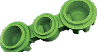
- ABS: Variations of ABS mimics include a clear, low-viscosity resin that can be finished clear; an opaque black plastic that blocks nearly all visible light, even in thin sections; a clear, colourless, water-resistant plastic good for lenses and flow-visualisation models; and a green micro-resolution resin that enables production of parts with extremely fine features and tight tolerances.
- Polycarbonate: A ceramic-filled PC material that provides strength, stiffness, and temperature resistance, but can be brittle.
- SLArmor: A nickel-plated material that gives SL-generated parts much of the strength and toughness associated with die cast aluminium.
Please note the term “thermoplastic mimic.” This is an important distinction in that the mechanical properties of SL materials only mimic those of their moulded counterpart. If you need to pound on your prototype with a sledgehammer, or leave it in the sun for a few months, be aware that SL parts do not provide the same strength and durability as parts that are sintered, cast, machined, or moulded. This makes SL the logical choice for prototype parts where validation of form and fit—but not necessarily function—is the most important factor. Customer service engineers at Protolabs can help guide you during material and manufacturing process selection if help is needed.
A Fine Resolution
Despite differences in material properties, SL is the clear winner over SLS in terms of part accuracy and surface finish. Normal and high resolutions are available, providing layer thicknesses ranging from 0.1 to 0.025mm and part features as small as 0.05mm. This means very fine details and cosmetic surfaces are possible, with minimal “stair stepping” compared to printed parts built by processes like fused deposition modelling (FDM).
SL also has the edge in part size—need a prototype of a new luggage casing, or a lawnmower shell? There’s a good chance SL can accommodate. Protolabs current max build size is 736mm by 635mm by 533mm.
Other Considerations
Stay away from extremely small holes as well, since the relatively high viscosity of the photo-curable resin used with SL can pose challenges during the post-build process. If you’re inventing a new-fangled angel hair pasta strainer, one with holes smaller than 0.12mm., SL is probably not the best choice for a prototype. Thin walls should be monitored as well. The lid for a hi-tech sandwich container, for example, should have walls no less than 0.75mm to 1mm thick.

Bear in mind that we may create temporary structures to support your part during the build process, but these are removed prior to delivery and typically little evidence of their existence is found. We may also choose to orient the workpiece to facilitate a better build, in which case the cosmetic appearance of some surfaces can be affected—if certain cosmetic features on your part require an elevated level of surface finish, please indicate those surfaces when submitting your design.
3D CAD File formats for SL
As for preferred 3D CAD file formats for SL, Protolabs accepts STL files. Most commercial CAD systems can generate STL files, the native format of any SL machine, but if yours doesn’t have this capability, our advice is to submit a neutral file format—such as an IGES or STEP file. But steer clear of the freeware STL generators littering the Internet. Some tend to create incomplete STL files, meaning additional rework time and delayed production.
An unfortunate limitation of the STL format, is that it is dimensionless. This means the file contains no internal description of the units used to create the 3D model when it was output. For example, the file may describe a box that is 1.0 x 1.0 x 1.0, but without knowledge of how the file was created, the dimensions could represent mm, inches, centimetres, or even metres.
Some CAD systems will default to saving in the native units used to model the parts, but others may choose to save in a standard unit, that could be different. This can lead to confusion as to the actual dimensions of the part to be produced. For example, should the part be modelled in mm, and the CAD system be set to output the model in cm, the additive part would turn out a factor or 10 times too small.
Most systems, when saving the file will allow the user to select options to verify the settings used to save the file. In the example screenshot below, taken from AutoCAD Inventor, note the selection box for units. The user will want to check that the correct units are selected, so that correct unit information can be entered in Protolabs instant pricing for Additive parts
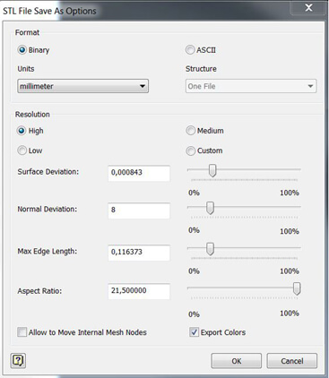
The resolution settings define how much detail is output to the file. Since the STL format represents the part with a mesh of triangles, a low-resolution setting can create a file where the triangles are too large. This can yield a file with large facets which can be visible on your prototype. For most CAD systems, the resolution settings of “High” or “Fine” usually create high quality files.
SL plays an important step in the design process. It bridges the gap between digital models and machined or injection moulded parts, giving people the ability to touch and feel prototype designs within days. Costly mistakes can be avoided, development costs reduced and better products built in the long run.
Check out protolabs.com/en-gb to learn more about stereolithography and the key design guidelines for building better SL parts.