


Ejector Pins
Your masterclass in product design and development
Protolabs’ Insight video series
Our Insight video series will help you master digital manufacturing.
Every Friday we’ll post a new video – each one giving you a deeper Insight into how to design better parts. We’ll cover specific topics such as choosing the right 3D printing material, optimising your design for CNC machining, surface finishes for moulded parts, and much more besides.
So join us and don’t miss out.
Insight: Ejector Pins
Transcript
Hello and welcome to this week’s Insight.
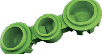
Ejector pins are the silent helpers of the injection moulding world. They’re utterly vital to the process of creating parts, but if all goes well, they leave barely a mark on them. Or, at least, that's the plan.
The entire point of the ejector pins is to apply a bit of force to the part, but sometimes this ends up leaving a bit of evidence behind. An important aim is to design and position things to minimise this kind of thing.
This involves some careful consideration of how we position the part, where we put the pins and where the gate – or possible gates – go.

There are a handful of factors we consider when we’re talking to customers about placement, some of which are fairly obvious.
For example, the shape of the part itself plays a prominent role, as things like the draft and texture and depth of walls and ribs can make some areas more likely to cling to the mould than others, and that’s where we want to be placing the pin.
The resin we’re using can also play a role, as some are stickier than others. Similarly, if the resin is particularly soft, we’ll want to use more or wider pins to spread the force around and prevent any damage.

Not everything is quite that simple, though, and sometimes our positioning will have to shift around based on some quite specific qualities of the part.
Among these is the fact that the ejector pins need a flat pad to push against, the surface of which has to be perpendicular to the direction of pin movement. If it isn’t, the force might be concentrated in just one tiny area, which is a sure-fire way to end up with dents or blemishes.
Of course, not every part in the world comes with solid, flat sides to press against, but even then, there are ways around this issue.

In some cases, it might be possible to carefully machine the end of the pin to match the contour of a part surface. To be clear, though, this is something done on a case-by-case basis, so you’ll probably have to have a chat with your engineers to see if this is a possibility.
Instead, the default solution for this is using a pad that is slightly recessed into the part surface.
There are a few different ways to set this up, with the most common being the centre-cut pin. This means that the pin hits the tangent of the angled surface, with half indenting the part and half hitting the raised pad on the part.
There are a couple of other options though, including shortest - which leaves the standing pad under the pin – or longest, which fully indents the pin into the part.
The most extreme example of a raised ejector pad comes in the form of a post gate, in which resin is injected through an extension of an ejector pin channel. When the part cools, the ejector pin pushes against this little post of resin and pops it out of the mould. The downside to this, as you might expect, is that you need normally need to remove this post after the fact.
This may not always look too pretty, but in most cases all traces of the ejection process, including pads and marks, are placed on the non-cosmetic sides of parts so you shouldn’t have to worry too much.
Now, all the examples we’ve been talking about until now assume that there are surfaces that the pins can push against, but it’s worth taking the time to think about what you’d do if confronted by some strange edge-cases.
What if we’re making, say, a grate, in which all that faces into the B-side mould half are the tops of ribs? They probably don’t provide enough surface area for the pins to push against, so you’re going to have to deploy a bit of lateral thinking and stick in some bosses to act as ejector pads.
If this all sounds a bit complicated, don’t worry too much. In most cases, ejector pin placement is a relatively minor concern in the early phases of part design. Your manufacturers will propose the locations and talk through what they mean before you sign off on them, so you should always have all the relevant information at hand.
That’s it for this week. I look forward to seeing you again next Friday.
With special thanks to Natalie Constable


