


6 Ways to Achieve Undercut Success in Moulded Parts
If your part design requires undercuts, consider side-action cams, bumpoffs, inserts, and other complex injection moulding techniques
Undercuts are those features in an injection-moulded part that prevent its ejection from the mould. With straight-pull moulds such as the ones used by Protolabs, these are any protrusions, holes, cavities, or recessed areas in the part where alignment is not perpendicular to the mould’s parting line.

Some examples include the threads on an injection-moulded fastener, the hole running down the length of a plastic hose barb, the slot for the power switch in the side of a smart phone case, an angled boss on the exterior of a hydraulic manifold, and the locking tabs on the base of a taillight lens.
There are many more such parts, all of which require a little moulding legerdemain—or minor part design modifications—to accommodate. This month’s design tip covers these techniques:
- Parting lines
- Side-actions
- Bumpoffs
- Hand-loaded inserts
- Part design and secondary operations
1. Parting Lines
Sometimes the easiest way to deal with an undercut is to move the mould’s parting line to intersect it. Need a square or round standoff as a locating or locking feature on a motor housing? Because of the draft on the outside of the part, you might be able to move the parting line and adjust the draft angles to intersect these standoffs. In some cases, multiple features can be dealt with in this manner, by zigzagging the parting line to intersect each feature. However, mould orientation and parting line placement is also dictated by part geometry, material flow, and a host of other factors, so be prepared for Plan B—perpendicular side-actions.

2. Side-Actions
Consider a tubular-shaped part, as in the hose-barb example. This is a great case for a perpendicular side-action, which can be used to form the hole running lengthwise in these and similar parts such as control knobs and screwdriver handles. Here, the mould halves are split horizontally along the long axis of the part. When the moulding cycle begins, the mould closes and the side action slides on an angled pin at the same rate so they are seated shut at the exact same time. Molten plastic is shot into the mould, and held for a short time to cool. As the mould opens, the side action again slides on the angled pin at the same rate until the side action is retracted far enough for the undercut to be free from the part when it is ejected.
Side-actions are limited to 213.84mm wide by 60.38mm high, and the maximum travel cannot exceed 73.66mm. These are the requirements for the side actions to be automated, but alternatives to these dimensions may be possible using a combination of side action and pick-out that will be discussed later. Protolabs has produced many moulds with multiple side actions so you are not limited to only one per mould, but like always, part size, complexity, and multi-cavity moulds may limit the number of side actions and size of side action. The costs associated with using side actions may increase your tooling, but are easily justifiable in order to receive the features you require in your parts.

It’s also important to note that side-actions work best with rigid materials like nylon, polycarbonate, acetal, and so on, especially for very deep features. Rubbery, flexible materials are not the best bet, as they might stick to the cylinder upon retraction and inadvertently get yanked out of the cavity. For these materials, a bump-off might be best.
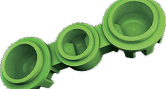
3. Bumpoffs
Bumpoffs are an easy way to mould lens covers, container caps, and similar parts with functions that call for them to snap into place. Rather than use a side-action cam, an insert is machined so the undercut can be applied and is bolted into the mould where a pocket matches the insert dimensions. During ejection, we rely on the plastic material to compress releasing the material from the undercut.
The bumpoff should be smooth and well-radiused, have a not-too-radical shape, and the material flexible enough that it can slip past the bump without tearing. Low-density polyethylene (LDPE) is an excellent choice, as are thermoplastic elastomer (TPE) and thermoplastic polyurethane (TPU).
Another consideration when looking at a bumpoff would be part ejection. You need to have adequate part ejection so the parts are not damaged by the ejector system poking through or into the parts surface. You may be required to add an ejector plate to the mould design so that we have additional mould surface area to eject from.
As long as we’re on the subject of flexible materials and bumpoffs, don’t forget about liquid silicone rubber (LSR) moulding, a thermoset process similar to plastic injection moulding. It is especially well-suited to seals, gaskets, and other parts requiring high flexibility, and offers fewer constraints on undercuts and complex part geometries than does plastic injection moulding.
4. Hand-loaded Inserts
How about a snap together plastic case for a medical device, say a handheld meter for diabetic blood analysis? It’s about the size of a deck of cards, and split into two equal halves. The bottom half contains a lip that runs along the inner perimeter for mounting a circuit board and other electronics. The lip is too tall and sharp for a bumpoff, and the parting line cannot be adjusted due to a series of holes along the outside of the case. What to do?
In this instance, mould inserts might be just the ticket. A machined piece of metal—or in this case, multiple pieces—are hand-loaded into the mould cavity, thus preventing plastic from flowing into these areas. Once the moulding cycle is complete, the inserts are ejected along with the part, whereupon an operator picks them out for reuse on the next part.
This manual intervention does increase cycle time slightly, unlike side actions that can still run on automatic. For prototypes and low-volume production parts, however, hand-loaded inserts are a good alternative to lifters or collapsible cores. Because the operator is handling the insert and parts that are at high temperatures, they are required to wear protective gloves that can impact the size of the insert. The inserts should not be small enough that they are difficult to handle, generally 0.500 in. square and larger are acceptable as long as they don’t exceed the approximate size of a deck of cards. The larger the insert, the heavier the part may be where the operator needs to reach outward two times a cycle and this can add additional strain on the operator.
5. Telescoping Shutoffs
The plastic case mentioned above brings up another common moulding technique. Telescoping shutoffs (aka sliding shutoffs) are often used to create clip- and hook-style mechanisms. These are commonly used for locking together the two halves of a moulded product, and in many cases can eliminate the need for side-actions, inserts, and bumpoffs that add more complexity to a mould. The “telescope” is machined into one half of the mould and extends into the opposite side during mould operation, “shutting off” certain part features.
Shutoffs offer an elegant way to simplify mould design and reduce product costs. Just be sure the part and mould have sufficient draft—add a minimum of 3 degrees from vertical, if possible—or else metal-on-metal rubbing might occur, creating flash or premature tool damage.
6. Part Design and Secondary Operations
When you upload your CAD model to protolabs.co.uk, you’ll receive a free design for manufacturability (DFM) analysis of your moulded part design. Undercut areas will be clearly defined, along with other mouldability concerns. Parts should have sufficient draft angles to assure easy part ejection from the mould. Wall thicknesses should be uniform and comply with the resin manufacturer’s min./max. thickness recommendations. Ribs should be used to support large flat areas. Internal corners should be radiused, thick section cored out to prevent sink, and fine finishes used only where needed.
A few final undercut tips:
- Be aware of the impact that undercuts might have on upfront mould investment and long-term product costs. It’s not always possible to eliminate them, but our application engineers will have some ideas on how to minimize their impact.
- It’s also important to discuss long-term product plans, so as to design the most efficient mould for your application.
- Don’t discount secondary operations. Using a drill press or milling machine to put a hole in a moulded part is sometimes more cost-effective than design a complex part in need of a do-everything mould, especially during the prototyping and low-volume production phases of your project.
Learn more about complex injection moulding techniques for undercuts with our white paper: “Designing for Mouldability.”
As always, feel free to contact us with any questions, at +44 (0) 1952 683047 or [email protected]. To get design feedback on your part today, simply upload a 3D CAD model at protolabs.co.uk for an interactive quote within hours.