


How to Choose the Right 'Boss' For Your Part Design
Building a better boss, a feature raised above a surface, depends on desired functionality
Princeton’s WordNet defines emboss as “raise in relief,” which is exactly what a boss is: a feature raised above a surface. In plastic part design, bosses are typically used to aid assembly, serving as a receptacle for a screw or threaded insert, or as a locator for a mating pin on a matching component.
Because of its role, a boss must have enough strength to perform reliably, which sets a minimum feature size. At the same time, a boss rises from the surface and locally increases wall thickness, which raises the risk of sink marks or internal voids as the part cools. The design goal is to size the boss large enough to meet functional requirements while keeping it small enough to avoid unnecessary sink at the base surface.
Boss Configurations Vary
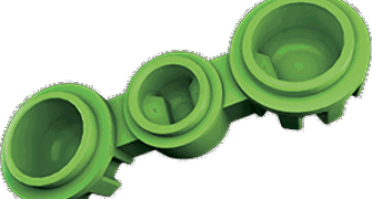
A typical boss is an open-topped cylinder, essentially a round rib (see figure 1a). Standard guidance suggests its wall thickness should be between 40 and 60 per cent of the thickness of the wall from which the boss rises. If greater strength is required than this allows, consider strengthening the boss without thickening its walls. The most common approach is to surround the boss with gussets to support and stiffen the walls (see figure 1b).
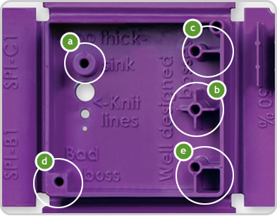
If a boss forms part of a vertical wall, the design should avoid creating a thick section in that wall. An example is shown in figure 1c. Similarly, when a boss sits close to a vertical wall, filling the space between the boss and the wall may be tempting, but it creates a thick area (see figure 1d). A better approach is to tie the boss to the wall with one or more ribs (see figure 1e).
In some cases, Protolabs’ milling process may require boss walls thicker than the standard 40 to 60 percent. Unlike steel tools that use core pins to form a boss’s internal diameter, Protolabs forms both the outside and inside diameters with features of the aluminium mould. When machining a relatively tall boss, a sufficiently small cutter may not be feasible to produce very thin walls. The issue can be mitigated by reducing the boss height to allow smaller diameter cutters, or a small amount of sink on the wall opposite the boss may be acceptable.
Other Considerations
There are two additional points to consider when designing bosses for injection moulding. A boss is a circular rib, and like any rib, both the inner and outer walls require draft to support reliable ejection. Depending on boss height, a draft angle of 0.5 to 3 degrees is typical. If draft on the internal diameter is not acceptable, the boss can be moulded as a solid and the internal diameter drilled as a secondary operation. Because a boss is formed by a blind hole in the mould body, vent pins may be added at the boss rim to allow trapped gas to escape during filling. Without adequate venting, short shots or burns may appear at the rim. As a manufacturing partner, we advise engineers on draft, venting and secondary operations to meet functional requirements and ensure consistent moulding.
Get A Quote
Ready to choose the right boss for your next injection moulded part? Upload your part for instant pricing and lead times.


