


Design for Machining Toolkit
Get in-depth design advice to optimise your plastic parts for CNC machining. Designing with machining in mind can accelerate production time and reduce production costs
Optimising Part Design for Machining
There are many design elements involved when creating plastic and metal parts for CNC machining — design for cost, design for quality, design for assembly, design for manufacturability. And navigating that landscape can be challenging at times. At Protolabs, we provide automated design analysis on CAD models that highlights features in your part design that can be adjusted for manufacturability. It’s a great design resource to have at your fingertips. To keep those manufacturability advisories at a minimum and optimise your part design, we created this helpful kit of different CNC machining resources.
Designing for Machined Parts
→ Tolerances
→ Holes
→ Deep Features
→ Threads and Inserts
→ Text
→ Radii
Navigating Critical Machining Advisories
→ Material Left Behind
→ Thin Walls
→ Holes That Can Be Threaded
→ Part Too Large

Designing for Machinability
CNC machining has been around for decades, and for good reason. It’s one the fastest manufacturing technologies for prototypes and end-use parts. Want to learn how you can optimise your product development cycles with CNC machining? This white paper shares how to design for the subtractive manufacturing process, select the best material for your application, and streamline new product development.
READ MORE
 part. It is the amount of acceptable variance in the dimension of a part. Typically, Protolabs will maintain a general machining tolerance of ±0.1 mm or better, however, our
  interpolated with an end mill rather than drilled. Apart from allowing for greater flexibility in hole sizes but also offers better surface finishes than drilled holes. The same tool is also used for slots and pockets, which means a reduction in cycle time and part cost. The principle trade-off is that holes more than 6 diameters deep become challenging as they normally need specific drills, which may mean the part needs to be machined from both sides.
 making, rather than the traditional "taps" used to manually create a thread. We use a single point thread mill to helically cut the thread profile, this CNC process produces an accurate thread and one tool can be used to cut multiple threads that share the same pitch (number of threads per inch). UNC and UNF threads from #2 up to 1/2 inch M2 to M12 (metric) are possible within a single tool set. The full list is
  long as space between characters and the stroke used to write is at least 0.5 mm
 as tungsten carbide, a super rigid material that offers maximum tool life and productivity with minimal deflection. But even the strongest tools deflect, as do metals and plastics that are machined.
 sharp corners on a part will be radiused (rounded). This will be identified before the part is milled. In softer materials, tools are flat bottomed so only the tool diameter needs to be considered. In Harder metals it is typical for tools to have a tip radius too – this will leave a small radius in the bottom of pockets. **
![]() Notes:
Notes:
* Try adding steps to buttresses to stiffen your design. Watch out for deep, narrow pockets, or part features situated alongside tall walls. Cutter or workpiece vibration could cause deflection, and a loss of accuracy or surface finish.
** Generally, radii are a good thing, fillets spread loads well, sharp corners can act as stress raisers and can initiate fatigue cracks. We deburr every part, but if you are considering adding external radii to improve cosmetics and handling, a 45° chamfer is quicker to machine and considerably more cost effective.
Remember for CNC:
- Internal corners—fillet or radii
- External corners—chamfer
Any part that requires square corners will cost much more, as the only way to produce them is to burn them out with electro-discharge machining (EDM) or to cut slowly with extremely small tools.
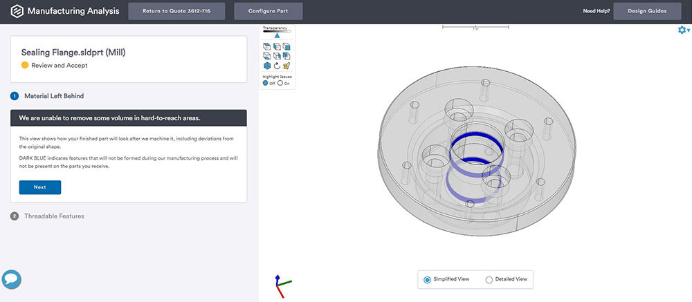 what will remain un-milled, deviating from your original design. Dark blue areas are those where material will be left behind or indicates where features will not be formed. You can decide whether to modify your design or leave with the changes as they are.
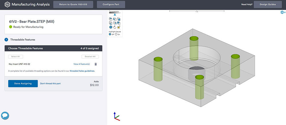 easily highlight and assign holes which need threads, by simply clicking on your 3D model.
 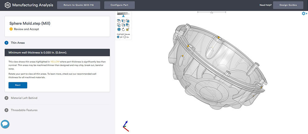 that are less than 1 mm, will be automatically highlighted as a thin wall geometry by the quoting system. You should keep in mind that we'll still allow it to be machined, so the machined part may differ slightly from your original design. Any thin walls below 0.5 mm risk breakage during machining, and flex or warp afterwards. Wherever possible, thickening them up is advised.

Enhanced Machining Capabilities with Our Digital Network
Get anodising, tighter tolerances, and volume pricing options through our network of manufacturing partners powered. You'll find plating (black oxide, nickel), anodising (Type II, Type III), and chromate coating at scale; tolerances down to ±0.020mm; and cost-efficient machined parts at higher volume.
Try Digital Network


Get an online quote and CNC machining design analysis today.