Prototyping with Polyjet
Your masterclass in product design and development
Protolabs’ Insight video series
Our Insight video series will help you master digital manufacturing.
Every Friday we’ll post a new video – each one giving you a deeper Insight into how to design better parts. We’ll cover specific topics such as choosing the right 3D printing material, optimising your design for CNC machining, surface finishes for moulded parts, and much more besides.
So join us and don’t miss out.
Insight: Prototyping with Polyjet
Transcript
Hi, it’s Friday which means it’s time for another Insight video from me.
Each week we take a look at a different aspect of additive manufacturing, and this week we’re going to talk about one of the very few industrial 3D printing technologies that allows the use of multiple materials in a single part build – polyjet printing.
Yep, where most other processes tend to limit you to one and just one material, polyjet can print several of them together in a single layer. This is great because it can allow you to combine different colours and hardness levels in a single layer that is just a quarter of the thickness of a sheet of printer paper.

On top of this, it provides excellent accuracy, as well as the ability to strategically alter material properties in a way never before possible.
If that doesn’t sound impressive, I don’t know what does.
While it can sound pretty futuristic, PolyJet has actually been around since 2005 and is a mature, well-understood technology that isn’t all that complex if you break it down. At a base level it works like traditional 3D printing processes, building parts from the bottom up one layer at time.
Where things start to get interesting is the print head. PolyJet uses a head equipped with multiple jets to spray tiny droplets of liquid photopolymer 42 microns across, to form layers just 30 microns thick.

To give you some idea of scale, a human hair is about 50 microns across. So, it’s pretty thin.
These layers are then rapidly cured by an ultraviolet light source, and when the build is complete, the part gets a quick bath in a chemical solution that dissolves the support structures that are printed along with the finished product, leaving surfaces that are smooth and accurate.
This all sounds great, but I’m sure that some of you are left wondering why? What’s the point in all this?
Well, I’m glad you asked. One of the most powerful aspects of PolyJet lies in its ability to mimic various polymers, including liquid silicone rubber and ABS. What’s more, those materials can be printed in a range of hardness levels, making PolyJet a perfect choice for prototyping an over moulded part with just a single build or run of the machine.

This all means that PolyJet is a great option for anyone who requires a fast, flexible, and accurate way of prototyping parts, but also needs the ability to incorporate multiple hardness levels or colours in a single build.
For example, we’ve seen automotive manufacturers use polyjet tech to prototype rubber seals and semi-rigid gaskets, digitally dialling in the hardness until it’s just right for their application.

In the medical industry it can be used to prototype orthopaedic implants and dental prostheses for fit-testing, or to create soft grips on hard plastic surgical instrument samples.

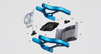
Two-toned electronics housings with clear plastic covers, flexible straps used on athletic equipment, complex appliance components, fine-featured but flexible snap-fit cases… The list goes on and on, folks.

This leads us onto our next point - what’s the catch?
Well, as with most other production technologies PolyJet 3D printing does come with a few design rules. Luckily for us, they aren’t too hard to follow.
First and most fundamental of these is that you have a maximum part size, depending on the size of the equipment you’re using. Here at Protolabs we can handle parts up to 490mm by 390mm by 200mm.

On the other side of things, you also have a minimum feature size. We’re looking at about 0.3mm in any direction, though if you’re talking about unsupported walls you need to more than double it, with functional or load-bearing features being a whole millimetre across.
It’s also pretty difficult to remove the support material on very small holes, slots, and channels - smaller than 0.75mm across, say. In fact, narrow features like this might not form properly at all, so be sure to keep this in mind on part designs.
Finally, if your part has any internal ‘land-locked’ shapes, like the inside of a cube or sphere, it’s tempting to make use of so-called weep holes to let the support material escape. While this is fine when the holes are large enough to allow rinsing of the support material, unless there’s a really compelling reason to do otherwise you’re probably better off just leaving them closed. Chances are you won’t even notice the trapped support material.

And that’s about it, as far as restrictions go.
In summary, if you’re designing a part that will be overmoulded, take a look at PolyJet.
If you’re prototyping a two-shot, injection-moulded part? PolyJet.
Need a part that’s rigid in one area but flexible in others? Polyjet
Translucent in some places and opaque in others? Yep. PolyJet.

I don’t think I need to say much more, do you?
Have a great weekend and I’ll see you next week.
With special thanks to Natalie Constable.


