


Nylon 3D Printing
Your masterclass in product design and development
Protolabs’ Insight video series
Our Insight video series will help you master digital manufacturing.
Every Friday we’ll post a new video – each one giving you a deeper Insight into how to design better parts. We’ll cover specific topics such as choosing the right 3D printing material, optimising your design for CNC machining, surface finishes for moulded parts, and much more besides.
So join us and don’t miss out.
Insight: Nylon 3D Printing
Transcript
Hello and welcome to this week’s Insight.
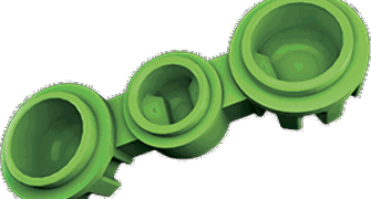
Today I’m going to talk about how to design for Nylon 3D printing.
Now, as I’ve said many times before, one of the great plus points of 3D printing is that you can design pretty much any shape or geometry that you want, so you may ask: why the need for design guidelines?
It’s true, you have way more freedom to do what you want when you are designing parts using 3D printing, and nylon is a great general-purpose material to use.
But when designing nylon parts for selective laser sintering and multi jet fusion there are five considerations to bear in mind to make sure that you get the parts that you want.
These are: adhere to minimum feature sizes, minimize part warpage, minimize differential shrink, design for powder removal and make sure you work with your supplier when it comes to part orientation.
Let’s take these points one by one.
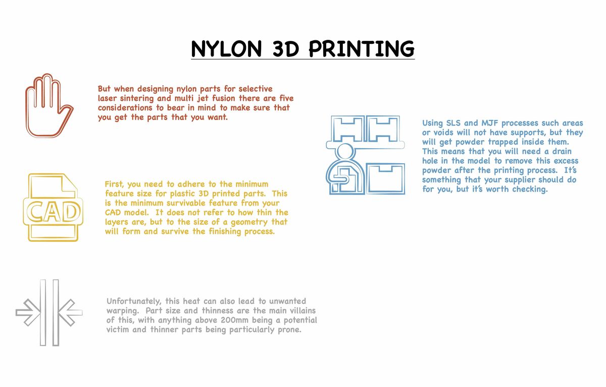

First, you need to adhere to the minimum feature size for plastic 3D printed parts. This is the minimum survivable feature from your CAD model. It does not refer to how thin the layers are, but to the size of a geometry that will form and survive the finishing process.
Common geometries that can cause problems are blind holes, threads, and tapers that are too close to exterior walls.
You also need to be aware of wall thickness in any direction or geometry and channel gaps.
For wall thickness we recommend a minimum allowable thickness of 0.8mm using SLS and 0.5mm for MJF.
A channel gap is the distance between two features. These are important in 3D printing because the sintering process can fuse two features together if they are too close. We recommend a minimum gap of 1mm for both SLS and MJF.

Now for number 2 on our list, minimising part warpage.
Powder based 3D printing like SLS and MJF use heat to sinter or fuse powder together to form a solid part. Unfortunately, this heat can also lead to unwanted warping. Part size and thinness are the main villains of this, with anything above 200mm being a potential victim and thinner parts being particularly prone.
If you are worried about your part warping, then you do have some options:
You can design the part close to a uniform thickness of 3mm for stability.
Opt for a glass filled or mineral filled nylon.
Check whether your supplier has a large frame SLS machine with build extends.
And finally ask if your supplier can cut and glue the part.
Okay now for point number 3 on our list, how to minimize differential shrink.
In some ways this is similar to warping in that it can occur when a part has different wall thicknesses. If one side of a part is really thick compared to the rest, it can cool at a different rate leading to undesired part shrink. If you do need a thick feature on the part, then we recommend hollowing it to a feature thickness of 3 to 5 mm.

Okay number four, designing to remove powder is due to one of the big pluses of using 3D printing. Using 3D printing you can design a part that minimises the amount of material needed by including internal void spaces in it.
Using SLS and MJF processes such areas or voids will not have supports, but they will get powder trapped inside them. This means that you will need a drain hole in the model to remove this excess powder after the printing process. It’s something that your supplier should do for you, but it’s worth checking.
The final point can help you reduce the risk of falling foul of minimum feature resolution or part warpage. Quite simply it’s how your supplier orientates your parts during production. I think that this one is best left to your supplier who should have plenty of experience using both SLS and MJF to produce the best possible part to meet your needs.
In fact, that final point is good general advice. It’s always a good idea to involve your supplier’s application engineers early in the design process. If they understand what it is that you are trying to achieve, then they can make sure that your design will succeed. Even better if they have an online system that check your CAD and highlight any issues for you – but that’s something for you to check with them.
That’s it for this week. I look forward to seeing you again next Friday.
With special thanks to Natalie Constable.


