


A Beginner's Guide to Injection Moulding
Everything engineers need to know about injection moulding, from design principles to material selection, in one comprehensive guide.
Injection moulding is one of the most widely used manufacturing processes for producing plastic parts at scale. This guide covers the fundamentals engineers need when moving from prototype to production, including how the process works, when it makes sense compared to other methods, design considerations, material selection, and quality control practices.
What is Injection Moulding?
Injection moulding is a manufacturing process used to produce large volumes of plastic parts with high consistency. Molten plastic is injected into a precision-machined mould, where it cools and solidifies into the final part shape.
The process is great for producing parts with tight tolerances, complex geometries, and consistent surface finishes, commonly used in medical devices, consumer products, and automotive manufacturing.
Rapid injection moulding services like Protolabs can deliver parts in as fast as one day, rather than the traditional months-long lead times, making short-run injection moulding viable even at lower volumes.
Injection moulding quick reference
- Ideal volume: 500–100,000+ units
- Standard lead times: 2–3 weeks (aluminium), 4–6 weeks (steel)
- Protolabs rapid lead times: From one day (aluminium)
- Typical wall thickness: 1–4 mm (keep walls uniform)
- Draft angles: 1–2° (polished), 3–5° (textured)
- Rib thickness: 50–60% of the main wall thickness
- Material shrinkage: ~0.1–3% (varies by resin)
- Common materials: ABS, PP, PC, Nylon (PA), Acetal (POM), PEEK
- Typical applications: Medical devices, consumer products, automotive components
When to Use Injection Moulding vs. Other Processes
Choosing the right manufacturing process means weighing key considerations like volume, lead time, part performance, and quality requirements. Injection moulding is often the best choice when you need production-grade materials, repeatable quality, and tight tolerances at scale, but it comes with upfront tooling time and cost. For low volumes or early validation, both CNC machining and 3D printing are usually faster.
How Does Injection Moulding Work?
Injection moulding works by forcing molten plastic into a metal mould, where it cools into shape and is then ejected. Before production starts, the mould is CNC-machined from aluminium or steel, then polished or textured depending on the surface finish you need. Once installed, production follows a repeatable four-step cycle:
- Clamping: The two mould halves are clamped together under high pressure.
- Injection: Molten plastic pellets are injected into the closed mould cavity through a nozzle.
- Cooling: The plastic cools and solidifies inside the mould. Cooling time directly affects cycle time and part quality.
- Ejection: Ejector pins push the finished part out, the mould closes, and the cycle repeats.
Cycle times range from seconds to a couple of minutes, depending on part size, wall thickness, and material.
Types of Injection Moulding
Injection moulding isn't a single process, but a family of techniques designed to suit different materials, part requirements, and performance needs.
| Process | Material Type | Typical Applications | Key Limitation |
|---|---|---|---|
| Thermoplastic moulding | Thermoplastic resins | Enclosures, housings, consumer goods | Single material per mould |
| Liquid Silicone Rubber (LSR) moulding | Thermoset silicone | Medical catheters, baby bottle nipples, seals | Longer cure time, higher tooling cost |
| Overmoulding | Two or more materials | Soft-grip toothbrushes, sealed connectors, multi-colour parts | Materials must be chemically compatible |
| Insert moulding | Plastic + metal insert | Threaded inserts, electrical contacts, reinforced bosses | Requires precise insert placement |
Design Principles for Injection Moulding
Designing for injection moulding means balancing geometry, material behaviour, and tooling constraints. Here are the key factors that affect part quality and manufacturability.
Wall Thickness
Maintain uniform walls between 1–4 mm. Thick sections cool slower than thin ones, causing sink marks and warping. Core out thick areas to keep walls consistent without adding weight or sink risk. When transitioning between wall thicknesses, keep changes gradual at 40–60% ratios. Crystalline materials (nylon, polypropylene) shrink more than amorphous materials (ABS, polycarbonate), making uniform thickness even more important.
Draft Angles
Draft is the slight taper that helps parts eject cleanly. Polished surfaces need 1–2° minimum, while textured surfaces require 3–5° due to increased friction. Without adequate draft, parts can stick, scratch, or require excessive ejection force.
Ribs and Bosses
Ribs are a great way to add stiffness without adding a lot of bulk. As a rule of thumb, keep ribs at about 50–60% of the wall thickness to avoid sink marks, and limit rib height to around 3–5× the wall thickness. For bosses, aim for an outer diameter about double the screw diameter, reinforce with ribs where you can, and keep boss walls at roughly 50–60% of the part’s standard wall thickness.
Radii and Corners
Sharp corners create stress concentrations. Use radii of 0.5–1× wall thickness at all inside corners. This improves material flow, reduces stress, and helps prevent cracking.
Tolerances
Tolerances in injection moulding depend on the material, part geometry, and how the tool is built. Shrinkage varies widely by resin (typically ~0.1% to 3%), and crystalline materials like nylon and polypropylene tend to be less predictable than amorphous plastics like ABS.
Tooling Considerations
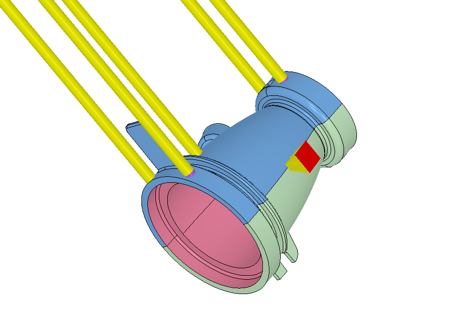
- Ejector pins leave small circular marks, so place them on non-cosmetic surfaces where possible.
- For logos and text, use sans serif fonts at 20+ pt with 0.25–0.38 mm depth. Raised text is usually easier to machine than engraved.
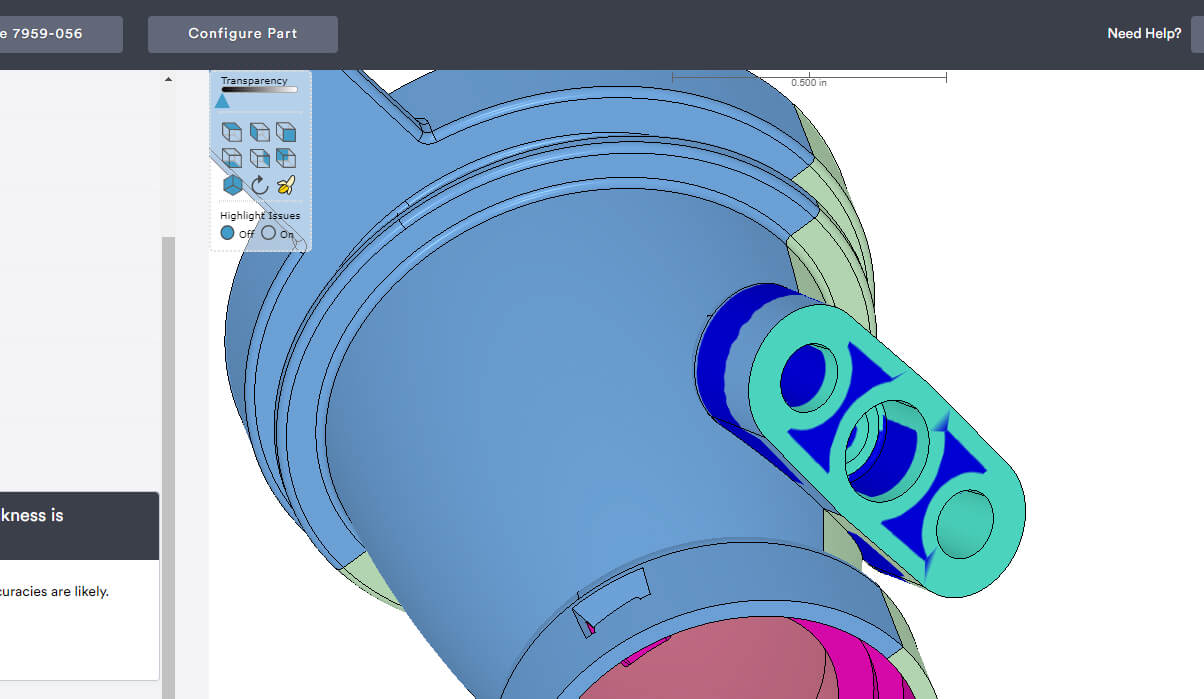
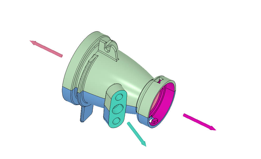
- Undercuts can lock a part into the mould, so they usually need side actions to release them. Each side action can add a few thousand euros to tooling cost and extend lead time. For cost reduction strategies, see our guide on tips to reduce injection moulding costs.
Gates
Gates control where molten plastic enters the cavity, which affects weld lines and surface finish.
- Tab gates: General purpose and often used for glass-filled materials
- Hot tip gates: Great for cosmetic parts and centre-gated designs
- Tunnel gates: Useful when you want automatic degating
If you’re designing for injection moulding, the Design for Mouldability Toolkit is a helpful reference for common design advisories like draft, wall thickness, and side actions.
Injection Moulding Materials
Material choice affects everything from strength and heat resistance to surface finish and dimensional stability. A good approach is to shortlist injection moulding materials based on your load, temperature, and tolerance needs.
- Commodity resins (PP, PE, PS): Lower cost, widely available, great for general-purpose parts.
- Engineering resins (ABS, PC, PMMA, Nylon, Acetal/POM, LCP): Better strength, heat resistance, or stability for functional parts.
- High-performance resins (PEEK): Built for high heat, chemicals, and wear, but at a higher cost.
The table below compares common injection moulding materials using typical real‑world ranges. Exact values depend on grade, fillers, and processing conditions.
Material Selection Quick Reference
| Material | Typical Shrinkage (%) | Tensile Strength (MPa) | Heat Deflection Temp. (°C) | Key Strength | Watch Out For |
|---|---|---|---|---|---|
| ABS | 0.4–0.7% | 35–50 | 85–100 | Tough, good appearance, easy to mould | Poor UV resistance, can warp with uneven walls |
| Polypropylene (PP) | 1.0–2.5% | 25–40 | 50–110 | Low cost, chemical resistant, great for living hinges | Higher shrinkage, less stiff than many engineering plastics |
| Polyethylene (HDPE/LDPE) | 1.5–3.0% | 10–37 | 40–100 | Tough, impact resistant, excellent chemical resistance | Can creep under load, higher shrinkage |
| Polystyrene (PS) | 0.3–0.8% | 35–55 | 70–95 | Low cost and rigid, can be clear | Brittle, poor impact resistance |
| Polycarbonate (PC) | 0.5–0.7% | 55–70 | 120–135 | Very high impact strength and good dimensional stability | Can scratch, needs higher processing temperatures |
| PMMA (Acrylic) | 0.3–0.8% | 50–75 | 85–105 | Clear with a great surface finish | Brittle, lower impact strength |
| Nylon (PA6/PA66) | 1.4–2.3% | 50–85 | 90–200 | Strong and wear resistant—ideal for moving parts | Absorbs moisture (dimensions can shift), can warp, especially when filled |
| Acetal (POM) | 1.5–2.1% | 60–80 | 100–170 | Low friction and good for precision parts | Sensitive to strong acids and oxidisers |
| LCP | 0.1–0.3% | 150–250 | 240–300 | Very strong and flows well for thin walls | Knit lines can be weaker, higher material cost |
| PEEK | 1.0–1.5% | 90–100 | 150–260 | High heat and chemical resistance, top-tier performance | Expensive, requires high processing temperatures |
Colourants and Additives
Colourants and additives let you tweak how a part looks, feels, or performs, without changing the base resin. Most resins come in black or natural (white, beige, amber, or translucent depending on the resin), but custom colours can be created by adding colourant pellets. Just note that tight colour matching can be tricky, and slight streaking is possible, especially with short runs.
Additives and fillers are used to boost specific properties like stiffness, UV resistance, conductivity, or low friction. They can be an effective way to hit performance targets, but they can also impact shrinkage, warpage, surface finish, and tooling wear, so it’s worth speccing them out early.
| Additive / Filler | What It Does | Common Benefit | Watch Out For |
|---|---|---|---|
| Short glass fibre | Reinforces plastic with chopped fibres | Higher strength and stiffness, reduced creep | More brittle, can increase warping, abrasive to tooling |
| Long glass fibre | Uses longer fibres for greater reinforcement | Very high strength and stiffness, reduced creep | Harder to mould thin walls or long flow paths |
| Carbon fibre | Adds stiffness and can dissipate static | Extremely stiff, ESD/static performance | Similar moulding limits to glass fibre, abrasive, higher cost |
| Mineral fillers (talc/clay) | Adds low-shrink filler particles | Lower cost, higher hardness, can reduce warping | Can reduce toughness, may affect surface finish |
| Glass beads / mica | Stiffens and improves dimensional stability | Lower shrinkage, reduced warping | High loading can make parts harder to inject |
| PTFE (Teflon) / MoS₂ | Adds lubricating particles | Self-lubricating, lower friction for bearing surfaces | Can affect strength and surface finish |
| Aramid (Kevlar) fibre | Reinforces with less abrasive fibres | Good reinforcement with less tool wear | Not as strong as glass fibre, can be costly |
| Stainless steel fibre | Improves conductivity for EMI/RFI shielding | Better EMI/RFI shielding than carbon fibre | Higher cost, can affect mould wear |
| UV inhibitor | Slows UV-related degradation | Better outdoor durability | Doesn’t make plastics fully UV-proof, still choose resin carefully |
| Antistatic additives | Helps parts dissipate static | Reduces dust attraction and static build-up | Performance depends on humidity and additive loading |
Surface Finishes for Moulded Parts
Surface finish is an important part of injection moulding because many moulded parts are cosmetic and intended for end-use. Your finish choice affects not just appearance, but also draft requirements and tooling cost. Below are common surface finish options for thermoplastic and liquid silicone rubber (LSR) moulding.
| Thermoplastic | Liquid Silicone Rubber (LSR) |
|---|---|
| PM-F0 (default): Non-cosmetic, tool marks acceptable | PM-F0 (default): Non-cosmetic, finish at Protolabs discretion |
| PM-F1: Low cosmetic, most tool marks removed | PM-F1: Low cosmetic, most tool marks removed |
| SPI-C1: 600 grit stone, matte | SPI-C1: 600 grit stone, matte |
| SPI-B1: 600 grit paper, semi-gloss | SPI-A2: Grade #2 diamond buff, high gloss |
| SPI-A2: Grade #2 diamond buff, high gloss | PM-T1: SPI-C1 + light bead blast |
| PM-T1: SPI-C1 + light bead blast | PM-T2: SPI-C1 + medium bead blast |
| PM-T2: SPI-C1 + medium bead blast |
Mould-Tech Textures
In addition to standard surface finish options, Protolabs also offers industry-standard Mould-Tech finishes for more complex textures. These can be used to improve grip on a part’s handle or hide cosmetic defects like parting lines. Mould-Tech textures can be used to achieve the following effects:
- Finishes produced by bead-blasting or polishing the mould surface
- Wood or leather-like graining
- Pebbled surfaces
- Matte, gloss, or hazy finishes, and many others
Post-Processing and Advanced Techniques
Injection moulding is often the main production step, but many parts need a few extra operations, especially if they’re assemblies, branded products, or include features that are difficult to mould in one shot. Here are a few common options and when to use them.
| Technique | What It Is | Best For | Why Use It | Watch Out For |
|---|---|---|---|---|
| Ultrasonic welding | Uses vibration to fuse two plastic parts together | Enclosures, housings, sealed assemblies | Fast, strong joints without screws or glue | Joint design matters, not all plastics weld equally well |
| Pad printing | Transfers ink onto the part surface | Logos, icons, instructions | High-contrast markings at scale | Can wear over time, available for ABS, PC, ABS/PC |
| Laser engraving | Burns a 2D image into the part surface or mould cavity | Permanent markings, serial numbers | Fast, durable markings without ink | No colour, contrast depends on the material |
| Pickouts | Removable inserts placed in the tool to form internal undercuts | Internal undercuts without side actions | Adds tricky geometry without major redesign | More manual handling and cost than shutoffs or side actions |
| Steel core pins | Steel pins used to form holes and tight internal features | Clean holes with little or no draft | Strong, smooth holes that release cleanly | Marks are usually inside the hole, but design still matters |
Quality Control
When you’re making thousands—or millions—of parts, quality control is what helps production manufacturing stay consistent. Protolabs offers a range of inspection options and process controls, including:
- Scientific moulding: A documented approach to developing and locking in process settings to reduce variation and improve repeatability.
- First Article Inspection (FAI): Inspection of initial parts to confirm they meet spec before full production.
- Production Part Approval Process (PPAP): A structured approval process used to prove a process can reliably produce compliant parts, commonly required in automotive and other regulated industries.

Frequently Asked Questions
What’s the minimum order quantity for injection moulding?
expand_less expand_moreIt often becomes cost-effective around 500–1,000 units, depending on part complexity and tooling cost. Below that, CNC machining or 3D printing are usually a better fit.
How long does tooling take?
expand_less expand_moreFor eligible parts, Protolabs can machine the mould and ship moulded parts in as little as one working day, with most projects delivering within 1–15 working days depending on complexity. More complex tools or steel tooling may take 2–6 weeks.
What causes sink marks?
expand_less expand_moreThick sections cool more slowly, pulling the surface inward. Prevent sink by keeping wall thickness uniform and making ribs and bosses thinner (about 50–60% of the wall).
Can I mould threads?
expand_less expand_moreYes. External threads are straightforward with enough draft, while internal threads may need an unscrewing mechanism, an insert, or post-mould tapping.
Ready to Start Your Project?
Upload your CAD file to get a free injection moulding quote, including pricing, lead time, and DFM feedback.