


While injection moulding is a relatively precise process, there may be very slight variations between your design and your finished part. Tolerance is the range of deviation in specifications that still allows your part to function as needed. This is especially important when your project involves multiple components that need to fit together during assembly. If critical tolerances aren’t met, your parts won’t fit or perform correctly.
In injection moulding, there are two different types of tolerances to consider: machining and resin. At Protolabs, our machining tolerance of +/-0.076mm refers to the tolerance built into the mould tool used. Our resin tolerance refers to the finished moulded part and can be greater than but no less than +/- 0.051mm/mm.
Let’s get into some key design, material, and process considerations that’ll help ensure key tolerances are met and that your moulded parts perform perfectly.
Designing for Mouldability: Part Dimensions
Designing with mouldability in mind is important. Our injection moulding design for manufacturing (DFM) analysis looks at a few key design advisories intended to improve the manufacturability of your part, should there be any design issues right off the bat. Here are a couple design best practices to ensure accurate dimensions in your finished injection-moulded part.
Wall Thickness
The thickness of part walls is one of the biggest contributors ensuring dimensional stability, which is critical to stay within tighter tolerance ranges. During the injection moulding process, there is a distinct time in which the resin is unstable as it cools and hardens into a completed part.
Thick parts tend to sink. Thick areas take longer to cool than the thinner areas. This can lead to divots and imperfections on the part exterior as the molten core shrinks inward and pulls the exterior walls with it. Warp is common in parts that don’t have consistent wall thickness, which means it may not meet the desired tolerance range. The best way to prevent these issues is to have consistent wall thickness throughout your part.
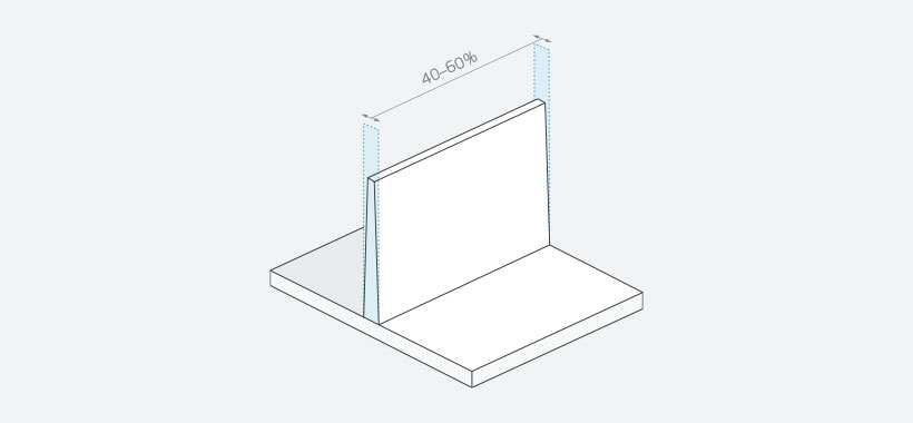
Proper wall thickness will reduce the risk of cosmetic defects in plastic parts.
Draft
Adhering to proper design principles is important when thinking about manufacturing constraints throughout the injection moulding process. For example, moulding requires draft for milling and ejection from the mould. If a designed part has assigned tolerances based on models that have too little draft, it will require changes to part geometry to be moulded effectively. Changes to draft angles affect part dimensions, and that, in turn, changes expected tolerances. As a rule of thumb, including 1 to 2 degrees of draft works well in most situations.
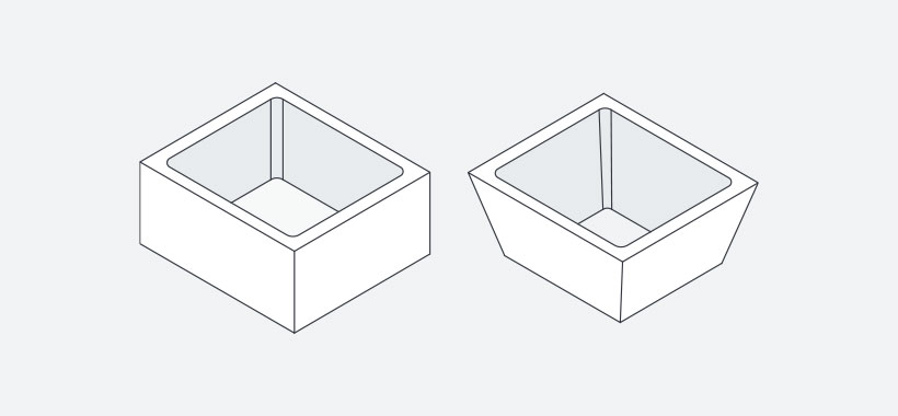
An undrafted (left) versus drafted (right) cube.
How Material Affects Molding Tolerances
Resin selection is crucial. Each material has different characteristics and melts, flows, and cools at different rates as it hardens into its final form. Determining the correct material for your application can make the difference between success and failure of your part.
Shrink
All materials shrink when cooling in a mould. Arguably, one of the most important characteristics of material selection is its shrink rate and it’s important to consider how the mould can accommodate it.
For example, say you’ve designed a mould for a part that will be manufactured using ABS plastic. ABS has a shrink rate of 0.076mm/mm. You’ll want to design the mould to accommodate the shrink of ABS plastic so the final part can match the desired tolerance of the nominal design. If you decide to switch to a polypropylene material with a shrink rate of 0.457mm/mm, the resulting difference is 0.381 mm/mm. Polypropylene shrinks at a faster rate than ABS, so the part will end up being roughly 0.381 mm/mm, and that might be a big problem.
In the end, you need to consider part design, material selection, and tool design together to ensure that you achieve your preferred tolerances.
Process Controls for Quality Parts
Protolabs uses scientific moulding, which optimises three parts of the moulding process: fill, pack, and hold. This process helps us deliver consistent parts, whether it’s the first, fifth, or hundredth run. It’s a sustainable process that ensures each manufacturing process is replicable and part dimensions remain consistent from run-to-run.
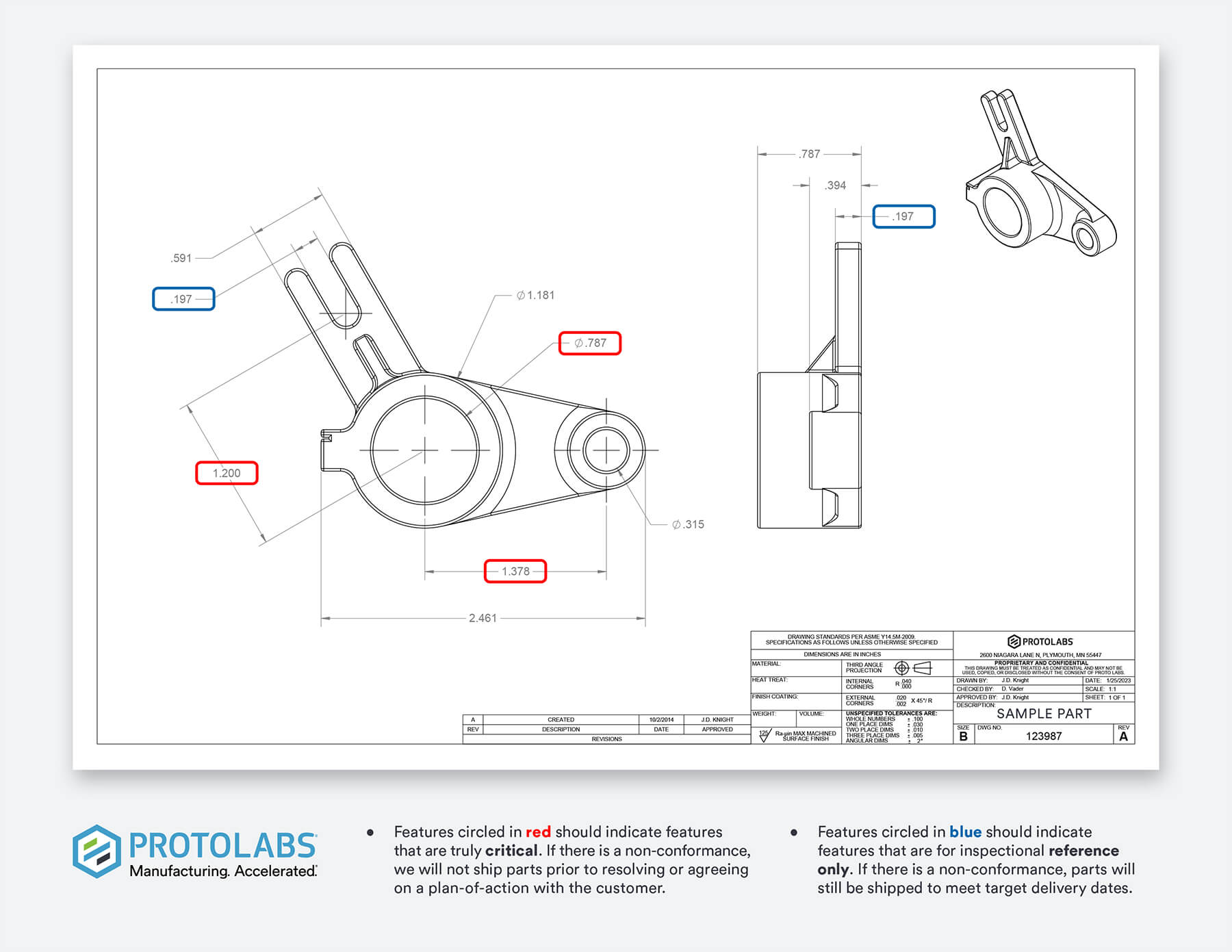
Certain features are more critical to the function of your product than others. That’s why we recommend that you call out up to five Critical-to-Quality (CTQ) features in your CAD model, including tolerances. It’s easy to do. Before you submit your CAD file, use a red circle to indicate your part design’s most critical features. Calling attention to the most vital specs helps us ensure we pay even closer attention to these features as we aim to meet your needs. CTQ allows us to produce parts that remain consistent for as long as we’re manufacturing them.
Design for Mouldability Toolkit
First things first. Once you upload your part, you’ll find our injection moulding design for manufacturing (DFM) feedback right in your quote. It highlights any advisories that may improve the manufacturability of your part. Follow the DFM tips and use the Design for Moldability Toolkit to guide you on making any needed changes to your part design. They’ll take you a long way to getting the parts you expect.

Need custom parts? Upload a 3D CAD file to get an online quote.
Get Custom Parts