


What is CNC Machining?
Explore design for machinability, material properties, finishing options, and more for milled and turned parts
Humankind has been drilling objects for millennia, but precision was always sort of elusive. When modern computer-based control of machines was developed in 1949 by James Parsons at the Massachusetts Institute of Technology, the aim was to make durable and consistent aircraft parts. While the first generation of CNC machining was still somewhat imprecise, it was a vast improvement. Parsons used the technology of the day—punched paper tape—to send instructions to the machine that told it where to move and where to mill.
We’ve come a long way since the days of punched paper tape spools. On some of today’s mills, the machining process can take place on five different axes without removing and restaging the part in a fixture, making for faster, more accurate output. CNC turning, which uses your 3D CAD models to create cylindrical parts, makes parts on a high-speed CNC-controlled lathe. With turning, it’s basically the same idea as cutting away slivers of wood from a maple log (or white ash, if you prefer) as it spins on its long axis, ultimately making a baseball bat. It takes time to do all this right, but we mill and turn parts 24/7.
How Does CNC Machining Work and What Are Its Benefits?
Unlike 3D printing, in which you add material to form a part, with CNC machining, it’s all about subtraction. You start with a solid block or cylinder of metal or plastic and cut away from it to achieve the desired geometries. It’s kind of a high-speed version of sculpture, but with drill-like cutters called end mills, instead of bits and chisels. For milling, the cutters—called end mills—spin at incredible speeds measured in the tens of thousands of revolutions per minute. Speed can be adjusted to avoid cutting errors or potential damage to more sensitive material. Sometimes slow and steady wins the race. CNC machining’s goal is precision, and feature tolerances can be as small as ±0.001 in. (±0.025mm).
Our entire process, from quoting to physical cutting in a mill—more commonly known as a machining center—or on a lathe is part of a digital thread, which ensures data integrity and helps maintain consistency. Essentially, we take your uploaded 3D CAD models and perform a design for manufacturability (DFM) analysis. Once any DFM issues are fixed in the CAD model and the quote is approved, the digital file is translated into G-code, a language that tells the machine how to cut away material to define the desired shape of the model as an actual 3D object. The mill or lathe then does the work as instructed until the part is complete, or so it can move to any desired finishing options—more about those later.
The thing to notice here is how this has all happened digitally. This simplifies communication and speeds production. So, the initial iteration can be done on the digital twin that our systems create, rather than with the traditional method that involves machining a part, followed by laborious back-and-forth discussions about how to adjust it, and more iterations until complete. With digital manufacturing, the goal is speed, efficiency, and accuracy once the physical part is produced.
Types of CNC Machines and Cutting Tools
But how does the machine know which kind of cutter to use? While you can choose any size end mill, we will direct you to the fastest solution to get your part finished. Each machining center (we have more than 500) comes with a set of standard end mills in various sizes. The mill set is chosen to offer a range of possibilities and is based on how often they are requested. Avoiding tool changes, and especially avoiding a change to a special, non-standard end mill, saves production time.
The technology behind machining has also come a long way. For many years, the standard lineup in any machine shop consisted of two-axis CNC lathes and three-axis machining centers. Some were horizontal and others vertical, but for the most part, work bounced between the two until all machining steps were completed. Lately, thanks to some clever machine tool builders, the line between lathe and mill has grown quite fuzzy. So called multitasking machines combine a milling spindle and tool-changer with a lathe-style head and turret (the part that holds the tools). Similarly, mill-turn lathes combine both rotating and stationary cutting tools, while machining centers with turning capability have become increasingly common. For example, we use lathes with live tooling to accommodate features such as axial and radial holes, flats, grooves, and slots.
Machining centers may also have more than three axes. A five-axis mill, for example, can move along all its axes simultaneously, an attribute that’s useful for producing parts like impellers and many other complex geometries. And a traditional three-axis machining center might be equipped with a head that tilts and/or rotates. This 3+2 capability is perfect for machining multiple sides of a workpiece in a single handling, avoiding re-fixturing, which always adds production time. Whatever the exact configuration—and there are many—each style of machine tool is designed to reduce machining operations and increase production flexibility.

Guide to Designing for Machinability
CNC machining has become a manufacturing staple for product designers and engineers who need low volumes of prototype or production parts, fast. This guide shares tips on designing efficient and manufacturable CNC-machined parts as well as how it can streamline your product development processes.
Advantages and Common Applications of CNC Machining
Whether prototyping or creating end-use parts, our CNC machining provides multiple benefits, including:
- quick-turn parts within 1 day
- precision and repeatability
- tight tolerances
- production-grade materials
- lower piece-part price at higher quantities
- robust post-processing that improves cosmetics and material properties
Compared to injection molding, CNC machining provides parts more quickly. Also, it offers greater dimensional accuracy than 3D printing (although this may change with further innovations) and produces parts with better mechanical properties in all three dimensions than 3D printing. However, CNC machining usually comes with a higher price tag, especially with smaller volumes of parts, and has less flexibility with complex geometries, compared to 3D printing.
As mentioned previously, CNC machining is a go-to manufacturing process to get precision parts, whether for prototyping or end-use production. It is widely used throughout the aerospace, medical, automotive industries for its ability to rapidly manufacture precise parts in production-grade materials, such as:
- housings and enclosures
- brackets
- fixtures for manufacturing
- gears and bearings
- internal mechanical components
- medical instrumentation
Quick Comparison: CNC Machining vs. 3D Printing
|
|
MACHINING |
3D PRINTING |
|
GEOMETRIC FLEXIBILITY |
|
X |
|
MECHANICAL PROPERTIES |
X |
|
|
PRECISION |
X |
|
|
PRICE |
X |
|
|
SPEED |
X |
X |
Basics of CNC Machining Design
If you’re someone who designs parts for a living, you might be wondering: Who cares? If I get my parts on time and at a reasonable price, it doesn’t matter to me how they’re made, right? Well, not necessarily. Just as you need to have a basic understanding of how a motor vehicle works to arrive safely at your destination, a reasonable grasp of machine tool technology is important knowledge for any parts designer. It is especially important when working with an automated digital parts supplier such as Protolabs, which can drastically accelerate the machining process—and often reduce costs—if certain design guidelines are followed.
The primer just offered is a good starting point, but the best advice short of programming and operating a machine tool for a few years is to work closely with your machined parts supplier. Ask questions, in particular ones such as: “How can I make my parts easier to machine?” With that in mind, here are eight considerations when exploring ways to optimize part design for machining:
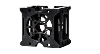
Keep It Simple
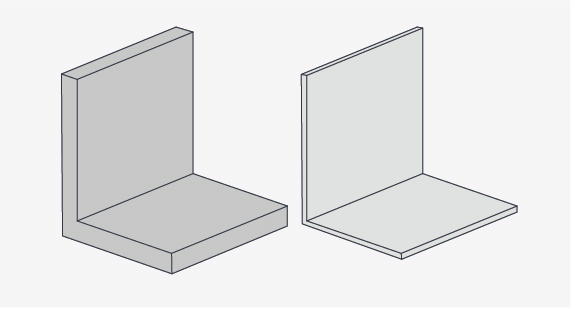
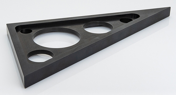
One of the most common mistakes that even experienced design engineers and product developers make is to overly complicate their part designs. Consider breaking up single-piece, multi-faceted “super parts” into simpler components that can be bolted, glued, or screwed together. Unless required for functionality, avoid swept surfaces, as these generally require lengthy, more costly machining with a ball-nose end mill. Design parts with features that can be cut from one side wherever possible. This avoids multiple operations and possibly special fixturing, as well as having to use a more expensive five-axis machining center, or one with tilt-rotary (3+2) capabilities.
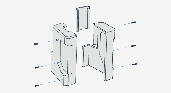
Although this could be manufactured as one large part, it would be difficult to do. Instead, splitting it into three and fastening the pieces together can speed lead times with the same quality result.
Sometimes, special cutters are needed to achieve tolerances on specific features on a part. This can add manufacturing time and cost to your parts. It's best to avoid tool changes. Just simplify and stick with the same tolerances throughout your part design.
Consider Part Tolerances—When Necessary
Making parts more accurate than necessary is another common mistake. When tolerances are tighter than needed, the machinist may be forced to modify the part program, use a special cutter, or even perform a secondary operation to meet that tolerance. Try to stick with the default “block tolerances” called out on any part drawing or ask your machining partner for advice as to what’s reasonable.
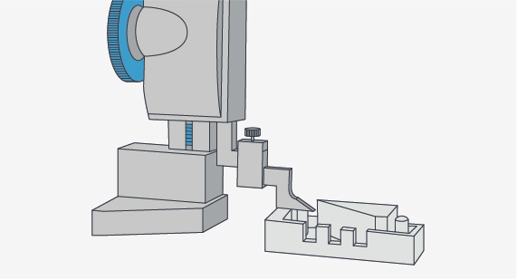
Stop Texting
Machined text looks cool. It’s great for permanently marking parts with numbers, descriptions, and company logos. The problem is, it’s expensive to produce. Each character must be traced with a tiny cutter, consuming valuable machine time. And don’t even think about raised text, as this means milling away everything that doesn’t look like a letter or number. Better options do exist, including laser marking or even a rubber ink stamp.

While you can engrave text into your parts, it does add lead time because of the need to use small tool diameters to precisely create the engraved content.
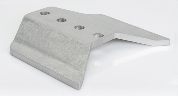
Leaving a bit more material at the bottom of a wall can strengthen your parts.
Use Caution with Tall Walls and Narrow Pockets
Cutting tools are made of hard, rigid materials such as tungsten carbide and high-speed steel (HSS). Despite this, they do deflect ever so slightly when subjected to machining forces, a phenomenon that becomes increasingly troublesome the farther out the tool protrudes from the toolholder—depending on the operation, carbide cutters are good to a “stick-out” of roughly 4x the tool diameter, maybe a bit more, on soft materials, while HSS tools become problematic at about half that distance. This leads to chatter (an ugly rippled surface), difficulty meeting part tolerances, and poor tool life. The lesson for a designer? Watch out for deep, narrow pockets, or part features situated alongside tall walls, or cutter deflection will create problems for those doing the machining.
Use Caution with Thin-Walled Parts, Too
Similarly, thin-walled parts are subject to deflection, but because most workpiece materials are nowhere near as rigid as the cutting tools used to machine them, the rules are a bit more stringent. Again, it depends on the part feature and material, but a good rule of thumb is to design walls that are no more than 2x thickness deep and understand that any wall thinner than around 1/32 in. will likely cause problems. As always, check with your machining expert for advice.
Watch out for walls that are too thin. They could flex, warp, or even break during the machining process or later when your customer gets the assembled product.
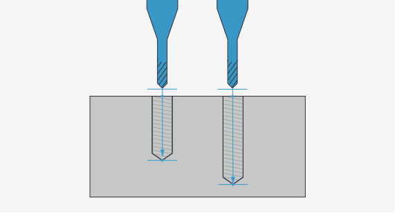
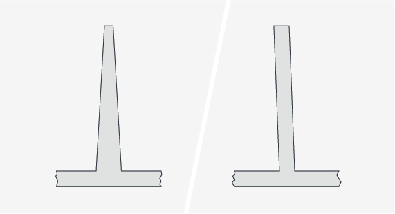
The end mill on the left should be able to create its hole. The end mill on the right is simply too short to successfully create the desired depth.
Drilling Deep Can Be Tricky
Hole-making is the most performed of all machining operations. It’s often done with drill bits that are a little different than the ones you find in any hardware store. As holes get deeper (say five to six times the drill diameter) evacuating the metal chips—called swarf—formed during any machining operation becomes increasingly challenging. If your product design requires deep holes, so be it, just know that the deeper they are in relation to their diameter, the more expensive the part or parts will be.
Navigating Sharp Corners
In machining, corners can be tricky, too. Say you’re designing an electronics housing for a product. On one side of the part you need a pocket, inside of which will sit a 2 in. square circuit board. Someone unfamiliar with machining practices might design a square-cornered pocket, one just slightly larger than the board itself to provide clearance. Not a good idea. Those square corners will cost you dearly, as the only way to generate them is to burn them out with EDM, a machining process common in the injection molding and tool and die industries. Space permitting, consider oversizing the pocket so that an end mill can be used instead—in this example, a 1/2-inch tool might be appropriate, which means adding half its diameter (1/4-inch) on all sides of the circuit board, plus whatever additional clearance is needed to fit the circuit board. Another option is to cut reliefs or “dog ears” at all four corners. This might give the pocket a cloverleaf or T-shaped appearance but will make machining much easier.
There’s plenty more to think about. Just as deep pockets are a no-no with milled parts, overly deep grooves can be challenging to turn, and long, slender shafts can be tricky, too. Breaking the edges on turned parts with a radius or chamfer is no big deal but requires an extra machining step on ones that are milled. And since we’re on the subject, be sure to ask your machining provider about its preferred method for deburring parts—some use abrasive wheels, while others “tumble” parts in small rocks, or blast them with tiny glass beads or bits of walnut shell. Each has its own advantages, and may affect the appearance of the finished product, as well as its cost.
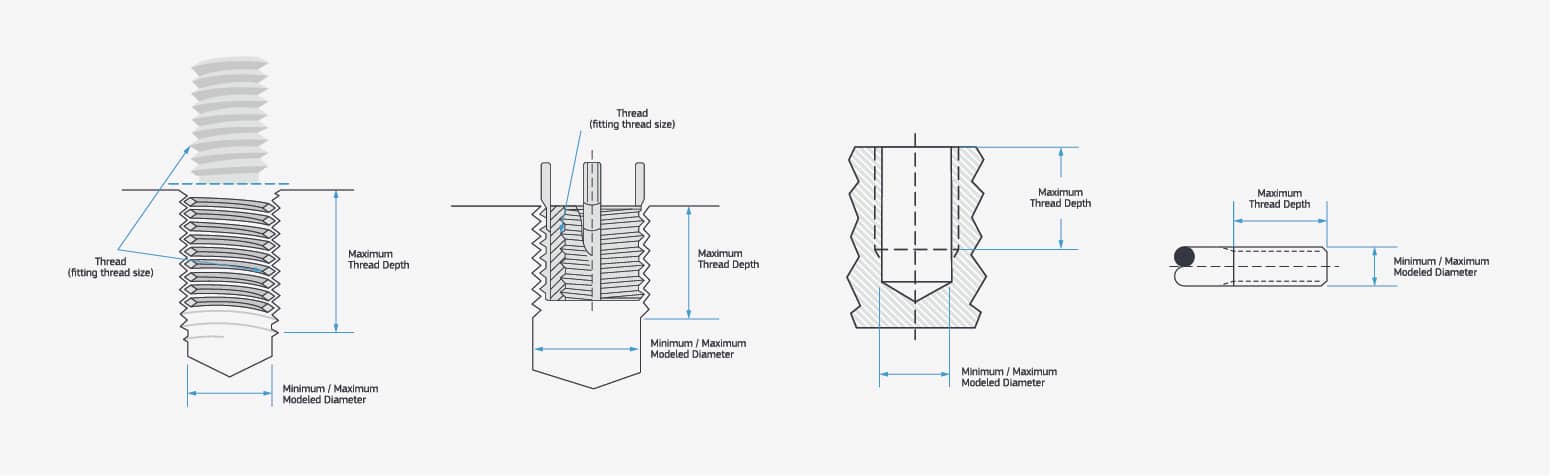
Designing for Accurate Threads
Internal threads can be created with a tap, a cutting tool that closely resembles the bolt or fastener that will at some point be screwed into the workpiece, or a special cutter known as a thread mill. Either way, deep threads are difficult for the same reason that deep holes are difficult, namely chip evacuation, and in the case of thread milling, radial cutting pressures. In most cases, a thread depth of twice the diameter provides plenty of strength, and costs less to produce. If this is insufficient, consider using inserts such as Heli-Coils or key inserts to bolster thread integrity, especially on plastic CNC parts. Finally, thread tolerances are specified with an “H” limit, the most common being H2 or H3. The latter has a tighter tolerance, however, and is therefore a bit costlier to produce, so the best bet is to call out an H2 for all but critical applications. Scroll down for more about threading.
Common Materials for CNC Machining
|
Material |
Properties |
Milling |
Turning |
|
Aluminum |
2024: Good fatigue resistance and strength; excellent toughness at moderate to high strength levels; improved fracture toughness 6061: Excellent machinability, low cost, and versatility 7075: High strength, hardness, low weight, and heat tolerance |
X |
X |
|
Brass |
Versatile and highly attractive copper/zinc alloy with warm yellow color accommodates severe forming/drawing |
X |
|
|
Copper |
High ductility and high electrical and thermal conductivity; develops attractive blue-green surface patina over time |
X |
|
|
Stainless Steel |
Excellent machinability and outstanding uniformity; good workability and weldability, high ductility and formability |
X |
X |
|
Steel Alloy |
Mix of chromium, molybdenum, and manganese yields toughness, good torsional and fatigue strength |
X |
X |
|
Steel Mild Low Carbon |
High machinability and weldability, high stiffness; good mechanical properties, machinability, and weldability at low cost |
X |
X |
|
Titanium |
Excellent strength to weight ratio, used in aerospace, automotive, and medical industries |
X |
X |
|
Material |
Properties |
|
ABS |
High impact strength, low heat conductivity, and low coefficient of friction |
|
CPVC |
High heat resistance yields excellent fire properties; corrosion resistant; high impact strength; excellent resistance to acids and alkalis |
|
HDPE |
Excellent impact, chemical, and corrosion resistance; high tensile strength; low moisture absorption |
|
LDPE |
High impact resistance; easy machinability; lightweight; safe for food; no moisture absorption; chemical- and corrosion-resistant |
|
PA (Nylon) |
Engineering thermoplastic with excellent mechanical properties; high chemical and abrasion resistance |
|
PC (Polycarbonate) |
High toughness; excellent impact strength; good machinability; can be optically transparent |
|
PEEK |
High abrasion and wear resistance; low moisture absorption; low coefficient of friction |
|
PEI (Ultem) |
Extreme strength, and stiffness, and chemical resistance, and high dielectric strength |
|
PET |
Excellent wear resistance and mechanical strength |
|
PMMA (Acrylic) |
Transparent rigid plastic often used as a substitute for glass |
|
POM (Acetal/Delrin) |
High mechanical strength, good dimensional stability, and low moisture absorption |
|
PP (Polypropylene) |
Excellent chemical resistance. Food-safe grades available |
|
PPE |
Outstanding mechanical, thermal, electrical properties; low moisture and low thermal expansion |
|
PPSU |
Exceptional hydrolytic stability, toughness; high deflection temperatures; outstanding resistance to environmental stress cracking; flame retardant; thermally stable; good electrical properties |
|
PS |
Good impact resistance; excellent machinability; good dimensional stability; low cost; some are safe for foods |
|
PTFE (Teflon) |
Excellent chemical and thermal resistance and the lowest coefficient of friction of any known solid |
|
PVC |
All-around good mechanical properties, excellent chemical and weather resistance, and good toughness |
|
UHMW |
High wear, chemical, moisture, and corrosion resistance; self-lubricating |
For more detailed information, including data sheets, for our machining materials, check out our materials comparison guide. Looking for metals like Inconel, Invar, or magnesium? How about plastic fiber like epoxy or Garolite? Try our digital network at Hubs.
Threaded Holes for Machined Parts
Our automated CNC machining service provides the ability to easily add threaded features to milled and turned parts. Threads are specified within our automated interactive quotes. When a quote is returned, the 3D display will show which thread types are possible for each feature. Different threads (where possible) or no threads can be selected on a feature-by-feature basis. View a sample quote to explore a 3D model with threads or check out our guidelines page.
For those having trouble with the interactive display, a 3D PDF is included in the demo quote that shows the thread options available. After an order is placed, an order confirmation will be emailed with the thread sizes selected. Please review the order confirmation for accuracy.
We offer a limited selection of UNF, UNC, and metric threads for machining along with coil and key inserts (but do not supply or install the inserts). On both milled and turned parts, threaded holes must be modeled at the proper diameter, however, threading options differ for milled and turned parts. Currently, automatic external threads are not available for milling. It is possible to machine approximate external threads using ball and flat end mills if threads are modeled and are at least 1/2-13 (M12) or larger. Threaded holes on turned parts are also available and external threads are offered on the axial diameters. Simply model the nominal diameter; do not model the threads.
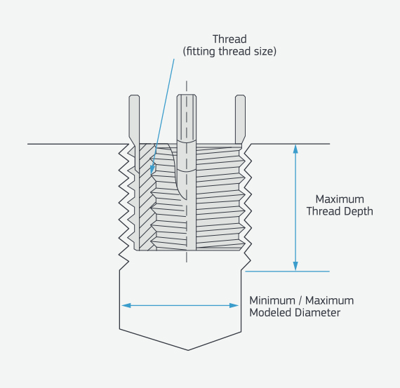
The key specs you need to consider when machining a thread.
Anodizing aluminum can protect your parts from scratches and corrosion.
Chromate-plated parts offer an attractive, protective finish.
Anodizing is typically used on machined aluminum parts to reduce corrosion and add an appealing metallic coloring to the porous aluminum substrate. It helps resist scratching, is a natural electrical insulator, and is one of the most durable finishes available. We offer three types of quick-turn anodizing options to protect parts:
- Type II
- Class 1 (clear)
- Class 2 (black)
- Type III (hardcoat)
- Class 1 (black)
Chromate conversion coating protects parts from corrosion by chemically changing the properties of the metal. It also offers electrical connectivity and the ability to paint a part.
- Type II, non-hexavalent (clear)
You can get finished parts within days (1-day expedite + 3 days for plating) at Protolabs. Here are the guidelines:
- Material eligibility: Aluminum 2024, 6061/6082, and 7075
- Non-cosmetic: Plug threaded holes, no masking available
Have AS9100 and ITAR requirements? Use our domestic precision machining option for anodizing. If you have more complex anodizing and plating requirements, work with our digital network of manufacturers. The network is ideal for when you require specialized color or other materials—such as titanium and nickel. Have AS9100 and ITAR requirements? Use our domestic precision machining service.
5 Things to Look for in a Machine Shop
Design considerations and best practices? Check. Raw materials? Check. Machine shop? That’s next. So how does one go about finding “the right stuff,” a shop with engineering expertise, reasonable pricing, quick turnaround, an online/interactive quoting system that includes design for manufacturability (DFM) analysis, and above all, the ability to make good parts on a consistent basis? Consider the following:
- Some shops specialize in low-volume and prototype parts, while others are geared toward production runs in the tens of thousands and more. Determining which part volumes any given manufacturer is most competitive with is an important first step.
- The most efficient shops are those that use standardized processes and toolsets. These reduce setup times, tooling costs, and above all, surprises. Don’t be afraid to ask a shop what makes it tick.
- Standard toolsets, however, have additional considerations to keep in mind. For example, a lathe or machining center with a fixed number of tools may need to make those tools perform double-duty—using an end mill to drill a hole, for instance, or a grooving tool to turn a journal or shaft. This approach, however, often produces the low cost or fast turnaround you need.
- We use an online-based, automated quoting system, which identifies features that are challenging to machine, upfront, before any production begins. This interactive design for manufacturability (DFM) feedback is beneficial in avoiding reworks by allowing for modifications early in the do design process.
- Look for a shop that can see the big picture and offers multiple manufacturing options. For instance, you might think that 3D printing is the clear path to quick delivery of prototype parts. This might be the case, but if your part design allows, machining is often a more affordable prototyping option. And what happens when part volumes rise? Designing parts for one specific manufacturing technology might very well paint you into an expensive corner. And, speaking of the big picture, make sure you also consider a supplier’s on-time delivery rate, its overall machining capacity, whether it is a service provider with in-house production vs. a broker, and its ability to scale from prototype quantities to low-volume production.
Importantly, don’t be afraid to ask questions, regardless of your experience level. We have experienced applications engineers (877-479-3680 or [email protected]) who can provide advice on design modifications and materials to improve the manufacturability of your parts and reduce part costs. Upload a CAD model today for a cost estimate, lead time, and automated design feedback.