


Navigating From Additive Manufacturing to Injection Molding
The precision and repeatability of industrial-grade 3D printing has established additive manufacturing as an effective and accurate process for functional prototyping. At the same time, plastic injection molding has long been a reliable and cost- and time-efficient way to produce parts for larger production runs of tens of thousands and beyond.
As a result, engineers, designers, and product developers have found that these two processes work well together in the life cycle of a product, starting with the design-risk mitigation of 3D printing prototyping and then shifting to the manufacturing method of injection molding to ramp up for higher volumes. For millions of part designs over the years, this has been a go-to combination.
At Protolabs, examples abound in several industries, including aerospace and defense and medtech.
It should be noted that there are several 3D printing processes that have the capability to build fully functional production parts. Direct metal laser sintering, for example, uses a range of metals to manufacture end-use parts. Selective laser sintering, using nylon-based materials, can create highly durable final parts. Multi Jet Fusion is also used to manufacture end-use, nylon parts.
That said, making the shift from 3D-printed prototypes to injection molding final parts remains a frequently used option, mainly, as mentioned, because molding is a more cost- and time-efficient way to produce parts in larger numbers.
When choosing this option, there are a number of unique design considerations to keep in mind. This post offers advice for navigating that shift:
- Defining a part before designing a part
- Using multiple prototypes
- Maneuvering through molding
- Choosing materials
- Mitigating costs and timelines

Design-Risk Mitigation: Defining a Part before Designing a Part
Prototyping with 3D printing or additive manufacturing is all about design-risk mitigation: Looking at how to improve a part’s design; looking at what potential risks there might be for a part’s form, fit, and function; trying out and vetting a variety of design concepts; and being mindful not to design one’s self into a corner by not accounting for the manufacturability of the part. Indeed, with 3D printing, there are few rules or limitations to cause problems for you when creating a part. But, to design a moldable part, well, that’s a different story. Function affects form for any type of part, but with plastic parts in particular, it also affects finish, and even the design of the mold that shapes them.
That’s where our automated digital quoting platform comes in. This analysis is especially crucial if you have in mind that the part will be molded, or at least produced in somewhat larger quantities beyond just the prototyping stage. For 3D-printed parts, you get an instant quote with interactive pricing based on material, resolution, and finish. Plus, you can always get design feedback from one of our in-house additive manufacturing engineers. For molded parts, you get an interactive online quote within hours, plus the DFM analysis, and real-time pricing based on quantity, finish, and lead time.
But let’s circle back to some risk mitigation examples. In the automotive industry, a part design that fits as a component of an SUV’s engine will likely need to survive exposure to high heat and humidity. This will drive key choices such as what material to use and what production method to opt for. It might require using selective laser sintering (SLS), a 3D printing process that can produce functional production parts, or maybe require molded or machining parts. Or, let’s say, a medtech company is prototyping a new, handheld surgical tool. In that case, a 3D-printed prototype would be a tool that would work fine in a doctor’s office or clinic for sales demonstrations and utility testing.
In this early front-end stage, the best advice is to use good, sound design principles to help with defining a part before designing a part. Which leads to the next section: the role of iterative or multiple prototypes.

Multi-Prototyping Helps Determine a Production Method
As mentioned, there are few rules or limitations with creating a part with additive manufacturing. That’s a blessing and a curse. It’s especially a challenge when designers want to transition a printed prototyped design to molded parts or another production method. Why? Well, in the case of molding, it “doesn’t like” thick cross sections, overhangs, flowing that goes around a core and knitting, complex geometry, internal channels or chambers, organic geometries, and so on. In other words, just because something can be 3D printed doesn’t necessarily mean it can be molded.
As a result, cross-quoting—quoting across or against multiple processes—along with iterative prototyping, can be a helpful vetting process to a part design. Doing this in parallel will help show whether the part will even be functional, and then how it might be successfully converted to the next step, to a method that allows for higher volume production, whether that might be molding, casting, machining, sheet metal fabrication, or other process. This multi-prototyping will likely also help you figure out price and time considerations, too.
In the case of injection molding, you will encounter more restrictions on what can and cannot be molded because if the mold cannot be produced, the part cannot be produced. For injection molding, lots of molding techniques and elements will need to be used or added (see next section on Maneuvering through Molding).
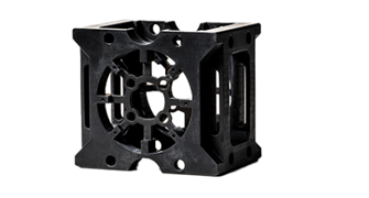
An aerospace industry example of this multi-quoting process occurred with the Lockheed Martin quadcopter drone (see sidebar box). The project designer, Miguel Perez, a Lockheed Martin engineer, worked with Protolabs’ DFM analysis auto-quoting system, which guided him through various part iterations, and eventually led him to shift from prototyping with 3D printing to both prototyping and low-volume production with injection molding.
He would submit an unmodified model to the quoting system and then get feedback, for example, on how the mold halves might work, suggested side pulls, and highlights of features that could not be molded. Perez would then use this information to make the 3D-printed part into multiple moldable interfacing parts that would preserve the design intent. Then he’d resubmit the modified parts and get yet even more feedback from the quoting system for how the mold might be made, showing him, for instance, where he may have overlooked required draft in appropriate directions.
A medical industry example is the verification testing that 3D printing provides for a part such as a Luer lock, which screws onto and fits on the end of syringes. There are certain ways to mold those locks to save costs but designs can be first validated with 3D printing, making sure it cinches down enough to make a seal, for instance, before deeming that it functions well enough to move it forward to molding.
Ultimately, depending on the part that’s being designed, testing and using multiple prototypes can help you verify whether something will work and help you gain more confidence in a prototype before making the leap to molding.

Maneuvering through Molding
To make that transition from printed prototypes to molded parts, a number of molding design methods should be considered and, when appropriate, applied. The top two of these techniques are uniform wall thickness and draft, though there are several others, too. Here’s a brief rundown:
Uniform Wall Thickness. Maintaining uniform wall thickness is probably the most important design requirement for getting good molded parts. Having uniform wall thickness makes it possible for the melted plastic to fill the mold evenly, therefore not creating a part with warp, sink, thin knit lines, or other defects.
Draft. Adding draft or slope to vertical walls of a part makes it easier to eject or remove the part from the mold. The primary rule is to apply 1 degree of draft per inch of depth to the mold cavity.
Radii. Use radii or rounded corners to improve the flow of plastic into the mold as well as the part’s integrity. Sharp corners raise the stress on your part and hinder the flow of the melted plastic (resin).
Ribbing, gussets, ramps. Including ribs and supporting gussets can increase the strength of structural parts and help eliminate warp, sink, and voids. Ribs should be 40 to 60% of the thickness of the adjacent wall. Ramps rather than sharp steps can reduce stress in shifts between thicker and thinner wall portions.
Bosses. Designing a thinner wall on a boss or mounting feature that will receive a screw will eliminate sink and voids.
For details on injection molding design guidelines, including part size and material recommendations, check out our design guidelines for plastic injection molding, which include maximum size dimensions, lists of commonly used plastics and surface finishes; liquid silicone rubber (LSR) design guidelines; and overmolding and insert molding guidelines.
Material Considerations for Injection Molding
The two broad categories of plastic materials are thermoplastics and thermosets (LSR for example). Choosing a material is based on a variety of considerations. The material’s mechanical, physical, thermal, and electrical properties are important. Manufacturability is essential, such as the characteristics of the resins (plastic materials in their raw form), including how resistant they might be to deforming during cooling and how well they fill small features of a mold. Depending on the part’s function, cosmetic appearance might also be important. Material cost is yet another issue. There may be other special considerations, too, such as a need for FDA or UL ratings.
Mitigating Costs and Timelines
Certainly overall costs and budgets, along with timelines and deadlines, are also key considerations. And, it may feel in some cases that cost especially is the top influencer of part or product development. Yet by using more affordable production methods such as molding, costs can be tamed.
Along these lines, a looming deadline may also feel like a top influencer. However, thanks to digital manufacturing methods that can accelerate product development, the prototyping and production of parts and products can be dramatically shortened.