


How to Design 3D-Printed Hinges
Learn how additive manufacturing can help you quickly prototype and improve your living hinge designs
Prototypes 3D printed with selective laser sintering (SLS) or Multi Jet Fusion (MJF) often include living hinges that will later be injection molded. Injection molding can create living hinges that are extremely thin yet still have a long lifespan. While it is possible to create robust and functional living hinges in SLS and MJF, more care needs to be taken in the design stage. This may even require that the hinge be designed one way during the prototyping stage, and then redesigned before moving to injection molding.
The first principle to keep in mind when designing a living hinge is that it needs to be the weakest area of the part. If the living hinge is roughly the same thickness as the rest of the geometry, then the part will distort and flex when attempting to use the hinge.
| WHY 3D PRINTING FOR LIVING HINGES? |
|---|
|
The force needed to bend a hinge is proportional not only to the thickness of the hinge, but also its width. Consider the possibility of modifying a hinge to several smaller hinges. For example, turning a 0.8 in. hinge into three 0.2 in. hinges and leaving 0.1 in. in between each hinge will not only extend the functional life of the part—if one of many hinges eventually fails, the part may still be usable—but could also improve the performance of the part. That's because less force is needed to operate the hinge and therefore less stress is placed on the clasps, snaps, and the geometry as a whole.
Note that a living hinge will act somewhat like a spring and will exert constant tension on the snaps, clasps, or whatever fastener is holding the part in the flexed position. These fasteners need to be robust enough to oppose the spring-like force of the hinge.

Materials for 3D-Printed Living Hinges
When 3D printing parts with living hinges, the most suitable nylon material is PA 12 available in MJF. Hinges can also be made from SLS materials PA 850 Black, and less preferably PA 650, however they will most likely have a shorter lifespan and greater care will be needed in designing them as well as the surrounding part.
We recommend avoiding PA 614 and PA 620 MF for parts with living hinges as the nylon is too stiff and will snap rather than bend. And while you could technically build a living hinge in an elastomer like TPU, the material will rarely be appropriate for the rest of the geometry.
How to Calculate Living Hinge Length
Living hinges are under constant stress when in use. One side of the hinge is under compression, while the other side will be under tension. Because of this, living hinges should be as thin as possible. This means that the thickness of the hinge should be the minimum feature size of the technology (0.02 in. for MJF and 0.03 in. for SLS). This is one of the reasons why MJF is the superior additive manufacturing technology for living hinges.
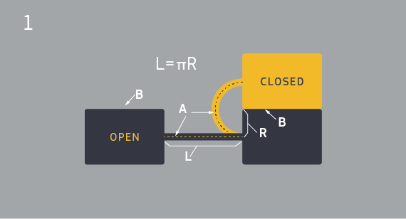
The formula L=πR is the ideal relationship between hinge length and placement. This allows the hinge to form a semicircle when in the closed position. Following this formula will evenly distribute the stress along the hinge and minimize stress at the attachment points. The following image demonstrates the relationship between hinge length and placement.
In Figure 1:
- A – Indicates the center of the thickness of the living hinge.
- B – Indicates the mating surfaces of the part.
- R – Indicates the distance from the mating surface (B), down the side of the part, to the center line of the living hinge (A). This will become the bend radius of the flexed hinge.
- L – Indicates the length of the hinge.
- Black – Indicates a cross section of the part/hinge in the unflexed or open position.
- Yellow – Indicates a cross section of the part/hinge in the flexed or closed position.
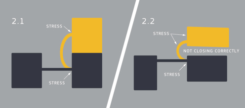
If the hinge is too short or the distance R down the wall to the attachment point is too large (L < πR) the hinge will be under tension in the closed position with the stress concentrated at the attachment points as shown in figure 2.1. If the hinge is too long or the attachment points are too close to the mating surface (L > πR), stress will be concentrated at the attachment points as well as the middle of the hinge. This also reduces the functionality of the part, as the excess hinge material will act as a spring, prying apart the mating surfaces as shown in figure 2.2.
 With these concepts in mind, we have found that MJF can build living hinges with good results after annealing down to length L=0.05 in. using the formula L=πR. Meaning that the minimum distance for R in the formula is 0.016 in. Due to how the outside of the hinge stretches relative to the center line of the hinge, smaller hinges (shorter length in the formula L=πR) put more stress on the material than larger hinges.
Larger hinges will put less stress on the material, and will therefore tend to have a longer lifespan. However, at some point the hinge becomes too large and may actually decrease the functionality and aesthetics of the part simply because of the size of the hinge feature.
A Formula for Right-Angle and Other Living Hinges
Up to this point we’ve only discussed hinges that have had a bend of 180 degrees; however, all of these principles can apply to any degree of bend, like a 90 degree hinge, for instance. So what’s the general rule for hinges of all bends?
In the case of a bend of 180 degrees (Figure 3), it is half of the circumference of a circle. So for a bend of 90 degrees, the hinge needs to become a quarter of the circumference of a circle. A general formula for the length of a living hinge given its bend radius (or vice versa), needs to use our previous formula: L=πR.
But since this gives the correct answer for a bend of 180 degrees, we need to take into account how much of 180 the bend degree in question is. In other words, we need to divide it by 180. A formula that can be applied to all bends is L=(Bend°/180)πR.
There is no guaranteed number of flex cycles your hinge will be able to withstand, but following these guidelines will help maximize the longevity of your 3D printing designs with hinges. If you need to discuss your 3D printing design in detail, contact our applications engineers at 877-479-3680 or [email protected].