


How to Design STL Files for 3D Printing in Your CAD Program
Try these tips to optimize your design for STL—the common CAD format used in additive manufacturing
We know you have a range of CAD programs and file format options to choose from when designing and sharing your part designs. The STL file, short for stereolithography, is the primary CAD file format that’s used for additive manufacturing (3D printing) design projects. This tip covers how to effectively design 3D-printed parts for STL.
What is an STL File?
Originally created and developed by 3D Systems and now supported by many other software options, STL is considered the preferred and standard file type to use for 3D printing. STL files describe the surface of the part by breaking it into a collection of triangles. The STL file lists the location of each point of every triangle as well as which side of the triangle faces outwards. Compared to other CAD file formats, STL files have relatively little information.
Tesselation and Resolution in STL Files
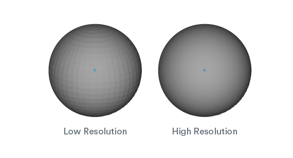
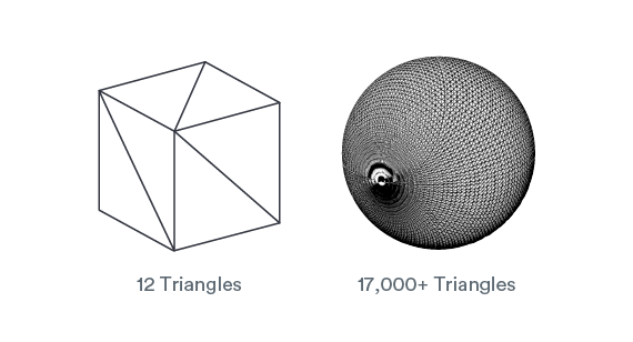
Tessellation is the process of dividing the surface of the part into triangles. If the STL uses too few triangles, curved surfaces will be faceted. These facets will show up on the printed part, so it’s important to make sure the STL has the correct resolution.
That said, more triangles aren’t always better. Parts that consist only of flat surfaces don’t require as many triangles, and using high resolution settings can increase the file size exponentially, without yielding a better part.
Deviation Tolerances and Angle Tolerances in STL Files
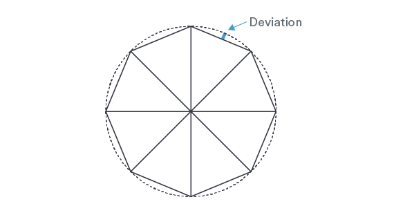
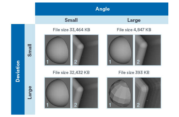
Deviation tolerance is the export setting that determines how far away the surface of the STL can be from the surface of the native CAD file. The lower the deviation value, the closer the STL file resembles the native CAD model.
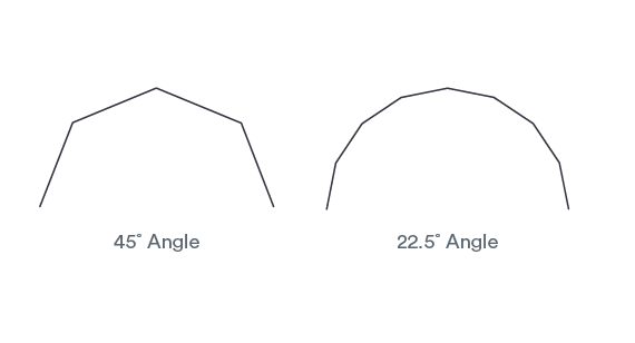
Angle tolerances is the export setting that refers to the direction a triangle faces compared to the triangles around it. The smaller the angle value, the smoother the transition between triangles. This setting is key for having the right resolution on fine features. As the angle tolerance gets smaller, file size increases significantly.
Choose the Right Angle and Deviation in STL Files
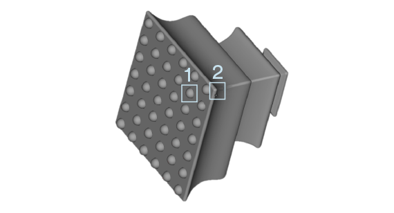
No settings will work for every single geometry out there. Best practice is to start with middle-of-the-road values for both, and adjust if needed. To check the resolution, open the newly generated STL and take a look. Since stereolithography (SLA) parts have a smoother surface than our other technologies, SLA parts are the most sensitive to faceting. Viewing the STL at actual size gives a good indication of whether facets will be visible on the final part. If fine feature resolution is critical, zooming in to check faceting in those areas is beneficial.

Keep an Eye on Units of Measurement
STL files don’t contain any information on units of measurement. For a 1.0mm by 1.0mm by 1.0mm cube, once the file is exported as an STL, it merely becomes a 1.0mm by 1.0mm by 1.0mm cube.
When uploading the STL for a quote, the units selected are applied to the STL. If millimeters are chosen, the result is correct, a 1mm by 1mm by 1mm cube.
However, if inches are chosen, the part becomes a 25.4mm by 25.4mm by 25.4mm cube (1.0 in. by 1.0 in. by 1.0 in.). The units can be chosen in the STL export settings.
Whichever units are used to export the STL are the units that should be selected when uploading to our website. In other words, designing and exporting both require units to be selected, especially in SolidWorks.
So, if designing in inches, export in inches, if designing in millimeters, export in millimeters. As seen in the illustration above, to make sure the correct units were chosen, check the part extents. In addition, use the Change Units feature to go back and correct the units if the extents are incorrect.

Combine Bodies to Successfully Export STL Files
In order to print successfully, the STL file needs to have a single, solid body. Overlapping bodies will tell the machine to draw twice in that area, which leads to build defects and build crashes in the machine.
Additionally, parts with overlapping solids are at risk for being priced too high, as the pricing system will read the STL and interpret it as having more material volume than it actually has. The illustration at right shows the distinction among one solid body, overlapping solids, and line-on-line solids.
For assemblies or part files with multiple bodies that need to be built as a single, merged part, the native CAD file needs to be modified so that it contains a single, solid body. Any components that aren’t intended to be part of the 3D print should be removed from the file. Hiding these bodies can cause errors when exporting to STL, so they should be removed entirely.
Once all extra bodies have been removed, all remaining surface bodies should be knit/stitched together to form solid bodies. Then, all solid bodies should be combined.
Make sure that no internal voids were created as a result of combining bodies. Some faces may need to be offset so that the solid bodies can be combined successfully. Once the native CAD file has only a single solid body, it can be successfully exported to an STL.
Exact procedures and language can vary by CAD software, however most have the same basic functions. Here are some useful resources for saving STL files and combining bodies in several popular CAD systems.
For questions on 3D printing or any of our services at Protolabs, please contact an applications engineer at [email protected] or 877-479-3680. Have a design ready for 3D printing? Upload it now for an instant quote.


