


Understanding 3D Printing Tolerances
Designing for accuracy and precision with additively manufactured parts.
Design engineers have long understood the importance of applying tolerances that align with a part's form, fit, function, and intended use. This holds true whether a product is machined, plastic-injection molded, or laser-cut and fabricated into a high-precision, highly functional assembly. And even though 3D printing is a comparative newcomer to the industry, appropriate part tolerances remain crucial for success.
To help designers looking for advice on the latter, here are some guidelines on the factors that affect 3D-printed part accuracy, expected tolerances by process type, and how we ensure that parts are accurate and repeatable from order to order.
What Are Tolerances in 3D Printing?
Note the term high-precision mentioned a moment ago. What does it actually mean? How does one go about applying tolerances to parts produced by one of a half-dozen or so distinct—often hugely disparate—manufacturing processes, all of which fall under the ever-expanding umbrella known as 3D printing?
To answer the first question, designers should consider the second F word in form, fit, function. It serves to determine whether and how well parts will fit together. This is the essence of any tolerance decision. For example, if you make the allowable deviation from a part's intended dimensions too generous, it either won't work as designed, won't fit properly with its mating components, or quite possibly, both.
And while there might be less chance of component mismatch when designers go the other direction—applying tolerances that are too restrictive—doing so serves to drive up manufacturing costs and possibly lead-time. In the case of 3D-printed parts, it could also require that designers change part geometry, use an alternative material, or even select a different process.
Key Factors Affecting 3D Printing Tolerances
As with any manufacturing process, 3D printing brings with it several unique considerations that influence part accuracy, and by extension, the tolerances that should be applied during the design phase.
Material Properties
The materials available to 3D printing part designers behave differently both during and after the printing process. For instance, SLA (stereolithography) provides fine finishes and high accuracy, but the ABS- and PC-like resins used here undergo slight shrinkage during the UV curing process. So do the nylon materials used in SLS (selective laser sintering) and MJF (Multi Jet Fusion), which shrink a bit as the parts cool.
On the other hand, metal parts made with DMLS (direct metal laser sintering) experience a small amount of thermal expansion throughout the build and during the subsequent heat treatment, both of which can affect final dimensions. In each case, our build prep team applies global offsets to accommodate these material-specific behaviors, ensuring that finished parts fall within specified tolerances regardless of the material selected.
Layer Thickness and Resolution
All 3D-printed parts are built one layer at a time, usually starting from the bottom and moving upwards. The thickness of these layers is known as the print resolution. Lower layer thicknesses—i.e., higher resolution—yield greater accuracy and finer detail but may increase build time and cost. At higher thicknesses (around 0.008 in. or 200 microns), visible “stair-stepping” can occur, affecting both aesthetics and dimensional accuracy.
This phenomenon is particularly noticeable on FDM (fused deposition modeling) parts and curved surfaces where the effect is often seen. By comparison, SLA can generate layers approximately 0.004 in. (0.1016mm) thick—about that of paper—providing excellent detail and surface finish.
Part Size and Features
The size of a part matters with 3D printing. That’s because, as part size grows—say anything the size of a banana or larger—dimensional inaccuracy accumulates due to thermal effects, potential warpage, and longer build times. That said, holes and other small features, even on very large parts, will generally exhibit good accuracy in and of themselves, although their positional location might be affected. With smaller parts, these effects are minimal, even when made of materials subject to greater shrinkage such as nylon.
Part Orientation
Part positioning and orientation within the build chamber can significantly affect both accuracy and surface finish. Vertically oriented parts might suffer lower adhesion between layers and cumulative errors that can stack up during the print. Both can affect final part accuracy. Flipping the part on its side with a flat or horizontal orientation offers increased accuracy because of the stable layering pattern but may be subject to differential cooling effects on parts with large surface areas.
Here again, our build prep team optimizes orientation to balance accuracy, build time, and part quality. For instance, we might apply a slight angle of 10° to 15° to reduce layer stepping while minimizing any differential cooling concerns. Further, a standard finishing process, such as bead blasting, helps minimize stair-step visibility and create a more homogeneous part appearance.
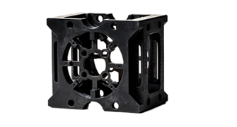
Tolerance Capabilities by 3D Printing Type
As with any manufacturing process, the various types of 3D printing technology offer different levels of precision, speed, and available materials. Because of this, designers should familiarize themselves with these capabilities to meet their anticipated accuracy requirements—the whole form, fit, function thing—while also respecting the project's budget and delivery date. Here's what you can typically expect from our 3D printing offerings:
- Metal 3D Printing (DMLS): Length and width (known as the X and Y axes) tolerances of ±0.003 in. (±0.0762mm) for the first inch plus 0.1% of the nominal dimension in each direction, with height tolerances (the Z axis) of ±0.006 in.(±0.1524mm) for the first inch plus 0.1% of nominal
- SLA: Tolerances in the X/Y axes of ±0.002 in. (±0.0508mm) for the first inch plus 0.1% of nominal dimensions, and Z axis tolerances of ±0.005 in. (±0.127mm) for the first inch plus 0.1% of nominal height
- MJF: Tolerances of ±0.012 in. (±0.3048mm) for the first inch plus 0.1% of nominal dimensions, regardless of the direction
- SLS: Tolerances of ±0.010 in. (±0.254mm) for the first inch plus 0.1% of nominal dimensions, regardless of the direction
- PolyJet: Tolerances of ±0.005 in. (±0.127mm) for the first inch plus 0.1% of nominal dimensions, regardless of the direction
Of course, these tolerances are also dependent on geometry and orientation, which is why designers should specify any essential dimensions as well as part features or surfaces during the quoting process.
Machine Maintenance and Process Control
Behind the scenes, maintaining consistent part quality involves rigorous process controls and routine machine maintenance. For laser-based processes (SLA, SLS, DMLS), we carefully monitor laser focus and power as both can have a significant effect on part accuracy, making it especially important that these parameters are checked before every build.
Environmental conditions such as chamber temperature and humidity are also tightly controlled, especially with powder-based processes like SLS and MJF. Here, bed temperatures are kept just below the material's melting point. This allows the energy source to fuse the powder with only a slight temperature increase.
Material quality management is equally important. Powder-based systems maintain a consistent ratio of used and fresh powder, providing for optimal mechanical properties while reducing part costs. For resin systems, tank contents are regularly replaced to prevent print distortions and ensure maximum part quality.
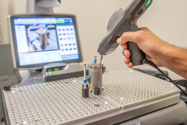
Quality Checks and Inspections
Whatever process or material was used to make them, all 3D-printed parts undergo inspection before shipping. Our standard quality control process requires visual and dimensional checks using calipers and gaging as needed to verify that parts meet dimensional tolerances and are free from physical defects. For those requiring a higher quality level, additional services are available. These include:
- First Article Inspection (FAI)
- CMM (coordinate measuring machine) measurements
- Laser scanning and 3D scanning reports
- X-ray and CT scanning (particularly valuable for DMLS parts)
- Material and process certification reports for compliance with ISO and AS9100 standards
The Need for Good Communication
While 3D printing continues to evolve rapidly, the principles of sound dimensional tolerancing remain timeless. This is why communicating with your customer service team is essential for success. With six different 3D printing technologies available, each offering unique advantages, our applications engineers can guide customers to the most appropriate process for their specific part and tolerance requirements. This, in turn, helps designers balance their functional needs and cost targets with achievable precision.
And as suggested earlier, customers shouldn’t hesitate to tell or show us which dimensions, surfaces, and features are critical, especially when tight tolerances are involved. Doing so allows the build prep team to optimize part orientation and process parameters to achieve the best possible accuracy where it matters most.
Have a design project in the works? Reach out to us at 877-479-3680 or [email protected].


