


How to Solve for Size Constraints, Small Gaps, and Thin Walls in 3D-Printed Parts
Navigating design for additive manufacturing advisories in your quote is easier than it seems, and it starts with thinking outside the box
There comes a time in many product development cycles when parts hit a seemingly immovable wall known as design for manufacturing (DFM), or in the case of 3D printing, design for additive manufacturing (DfAM). At Protolabs, this wall is most often represented by an advisory known as a Required Change, followed by some computer-generated text suggesting a possible course of action.
Such advisories might include the ominous words "Remove from Quote" or a more agreeable “Review and Accept.” Whatever the case, it’s important to recognize what the software is telling you and why it’s saying it. You should also know that, even when the automated quoting tool seems to indicate that your design is doomed and you might as well go home for the day, alternatives exist. This design tip will describe three of the most common red flags in 3D printing, and offer a few helpful suggestions on ways to deal with them.
Oversized Parts
The “Part too big” advisory is perhaps the most alarming because it's followed by the to-the-point "Remove from Quote" command mentioned a moment ago. Surprisingly, this manufacturing constraint is one of the easiest to work around, but before going into the how, let’s talk about the why.
As with any machine tool, 3D printers have set limits on axis travels, thus defining the maximum size of workpieces a given machine can produce. Unlike most CNC machining centers, lathes, or EDM machines, though, 3D printers don't require that the part sits in a horizontal or vertical orientation during the manufacturing process.
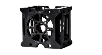
Consider a spur gear like the one shown in Figure 1. There are many ways to process such a part, but on a CNC machining center, it would most likely be clamped in a vise or fixture on the machine table, resting on the gear’s flat backside. The same can be said for the plastic injection mold used to produce this part, which would be milled or EDMed in the same orientation.
Constraint Workarounds
Let’s pretend that the designer would like to 3D-print a prototype of the spur gear before investing in the fixture, vise jaws, or possibly injection-mold the part. She knows that the stereolithography (SLA) printers at Protolabs can produce parts up to 29 in. x 25 in. x 21 in. (736mm x 635mm x 533mm) in size, easily large enough for the gear’s 13.78 in. (350mm) maximum dimension.
But because she would like the gear to be very smooth and accurate, she chose to have it printed at micro-resolution using ABS-like MicroFine™ Green resin. However, this selection limits the maximum part size to 5 in. (127mm) across, leading to the “Part too big” warning and subsequent note that the part will be removed from the quote.
Undeterred, the designer decided to leverage 3D printing’s ability to manufacture parts in any orientation, so she tipped the CAD model at an angle, sort of like squeezing an oversize birthday gift into a too-small box. She also selected high-resolution when submitting the quote, increasing the maximum part size to 10 in. (254mm) in each direction.
She quickly realized that tipping the gear means additional support structures are needed to constrain it during printing, thus increasing build time and part cost slightly. Sadly, she also found that the gear was still a bit too large by an inch or two, so she performed another additive-only magic trick—she sliced the part model into halves and modified it to include some mating pins and holes at the cut-line, intending to glue the pieces together after printing (a process that we call cut and bind). Problem solved.
Micro-Resolution and Accuracy
It’s worth mentioning that the manufacturing legerdemain described in the Constraints Workaround section—though clever—might be unnecessary. Protolabs customers often check the box for micro-resolution thinking they’ll get more accurate parts. That’s not true. What they will get are thinner part layers, therefore producing a smoother finish, as well as the ability to produce smaller part features. In this particular case, the designer would have been better off had she selected normal-resolution printing—which boasts a 29 in. x 25 in. x 21 in. (736mm x 635mm x 533mm) build size—and vapor smoothed the part afterward. Again, problem solved.
Jumping the Gap
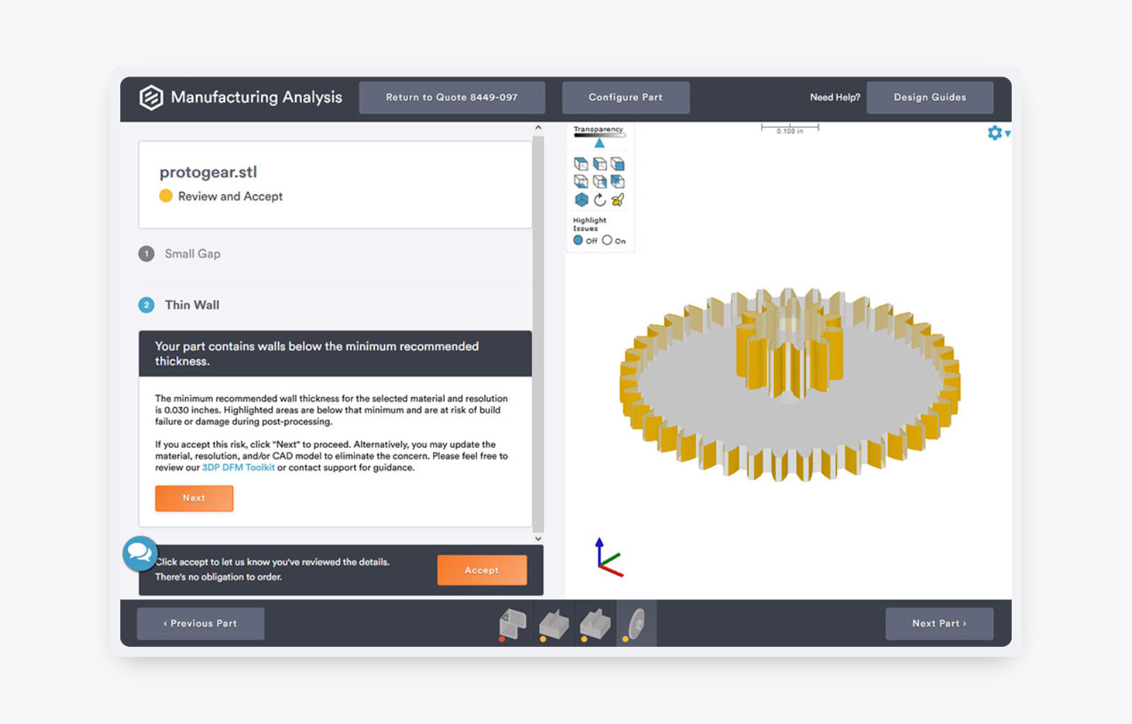
Now take a look at the Small Gap warning in Figure 2. This indicates that the distance between each of the spur gear’s teeth is less than the recommended 0.03 in. (0.75mm), and that, depending on the 3D printing process, raw material, part geometry and orientation, the customer can expect partial or even complete fusing between some or all of the teeth.
Here’s one place where micro-resolution shines. As noted earlier, it supports features down to 0.0025 in.(0.063mm) in the horizontal direction, one-half and one-fourth the size of high- and normal-resolution respectively. This statement also holds true for the Thin Wall warning seen in Figure 3. In this situation, the as-printed teeth might not meet the desired dimensional or geometric tolerances and could even break off during printing. Micro-resolution SLA and high-resolution direct metal laser sintering (DMLS) are the best option in each of these cases, size constraints notwithstanding.
Grains of Salt
Note the caveat from a moment ago, “depending on the 3D printing process, raw material, part geometry and orientation.” It’s critical to remember that Protolabs offers most of the leading additive manufacturing (AM) technologies and more than 30 different AM polymers, metals, and elastomers, each with its own unique properties and printability. This broad spectrum of manufacturing solutions means there’s little we can’t tackle, and that’s not counting our other processes: CNC machining, plastic injection molding, and sheet metal fabrication.
But due to this complexity, a short design tip like this can only scratch the surface of what’s possible or how to deal with any given design advisory. In our gear example, fixing a thin wall or small gap warning might be as simple as selecting a different polymer, or moving to a different 3D printing technology, or as we've seen, changing print resolution. It could also mean skipping the 3D printer entirely and prototyping the part using our quick-turn injection molding service, an option that's easier (and less expensive) than one might think.
The takeaway? Don't let red flags stop you. Use the automated quoting tool to get a quick price, narrow down your available options, and if you see something you don't like, don't understand, or can't figure out on your own, give one of our customer service representatives a call. And above all, don't be afraid to think outside the box.