


Pop Quiz: Between Figures 1 and 2, which one is easier to understand?
Figure 1
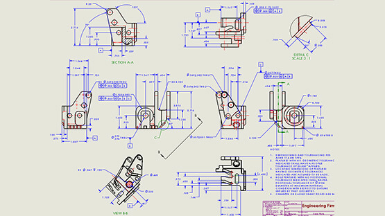
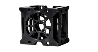
Figure 2
The answer is obvious. Figure 2’s 3D model is much more straightforward than Figure 1’s 2D drawing. We live in a 3D world and our cognitive minds understand 3D objects much more easily and quickly.
The comparison illustrates the communication advantage of Model-Based Definition (MBD), which has explicit or implicit annotations defined and integrated directly with 3D models. MBD can help reduce counterintuitive and ambiguous interpretations in 2D drawings. A favorable timing factor is that most of today’s engineering designs are constructed in 3D models already. Why do we have to project them down to a 2D plane just to add dimensions and tolerances?

MBD can also improve manufacturing efficiencies. For example, in a conventional way of Computer-Aid Manufacturing (CAM), a manufacturing engineer programs based on a model directly, but he or she has to read separate drawings to exact the tolerances and surface finishes, and then go back to the model and manually type in these requirements into the CAM program. The back-and-forth switching between models and drawings not only slows down the process, it also introduces potential human reading or typing errors.
In contrast, in a model-based environment, you can read everything in one place as shown in Figure 3 without having to switch back and forth between different documents. The models and requirements in annotations are integrated for easier reading.
Furthermore, the tolerances and surface finishes can be consumed and acted upon by the SOLIDWORKS CAM software so that you don’t have to manually read or type them. In other words, these intelligent annotations can automate the Numeric Control (NC) code programming one step further than the model itself.

What about inspection? Acting upon 3D geometric dimensioning and tolerancing (GD&T), CheckMate can automatically program coordinate measuring machine (CMM) paths and soft gauges. Plus, the CMM sample points or a 3D-scanned point cloud can be overlaid on top of and compared with the nominal CAD model. Then, CheckMate automatically generates a quality heat map per the intelligent 3D GD&T as shown in Figure 4.
Machining and inspection are just two examples. The intelligent 3D annotations can help automate many more manufacturing applications such as tolerance analysis, Computer-Aided Process Planning (CAPP), cost analysis, and so on.
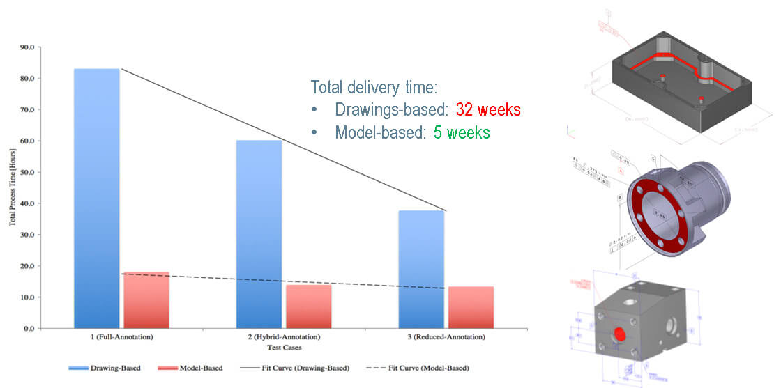
Of course, none of these would matter if there were no concrete benefits. Figure 5 shows a study by Rockwell Collins, its supplier Geater Manufacturing, and the National Institute of Standards and Technology (NIST): Testing the Digital Thread in Support of Model-Based Manufacturing and Inspection. The three production parts in this study are listed on the right of Figure 5. The research team compared drawing-based and model-based approaches side by side in three steps: annotation, machining, and inspection. It was found that the model-based approach saved over 60 percent of the total process hours across the three parts. The time savings primarily came from the automations powered by the intelligent 3D annotations.
Besides the total process time, the study also found out that the drawing-based approach took 32 weeks to deliver all three parts, while the model-based approach only took 5 weeks, or saving 85% of the cycle time. The reason was that there were 12 questions asked about the 2D drawings, which interrupted the production and introduced work stoppages, whereas no question was asked about the annotated models.
Besides the numbers, there are also significant product quality differences between these two approaches. You may find more details in the study report.
Because of the tangible benefits, more and more SOLIDWORKS users started to annotate 3D models to reduce 2D drawings as shown in Figure 6. On the Geoffrey Moore new technology adoption curve, you can see the percentage was very minimal in 2009— only 1.5%. But it has jumped substantially in recent years to about 25% in 2017, indicating MBD is becoming a majority technology going forward.
Now let’s see how to get started with MBD. Here are 12 free SOLIDWORKS MBD video tutorials on MySolidWorks, which walk you through several important steps including:
- Define 3D annotations.
- Organize 3D annotations.
- Communicate MBD data.
Oh, a few more things. Remember to ask your Protolabs contact about a discount for digital inspections on parts with 3D annotations embedded as opposed to 2D drawings. And check out Protolabs’ blog post that discusses Product Manufacturing Information (PMI) a bit more, and how it’s connected to digital inspections.
To learn more about SOLIDWORKS MBD, please watch the 22-minute webcast or find me online at Twitter (@OboeWu) or LinkedIn (OboeWu).
About the Author
Oboe Wu is the SOLIDWORKS MBD product manager with 20 years of experience in engineering and software. He is an advocate of model-based enterprise and smart manufacturing.