


Stocked Punch Form Tooling for Sheet Metal Production Applications

Form tools provide options to add functional or aesthetic shapes to your sheet metal designs that are not geometrically possible using traditional press brake tooling. We stock various feature types and sizes, using a punch press to apply them to your part.
During the punching process, form tools—made up of an upper tool (punch) with a lower tool (die)—shape the sheet metal material. The punch form tooling library shapes are available to incorporate into your design, helping you avoid high tooling costs and lead times that are typically associated with adding these features.
Our applications engineering team can provide insight into the best solution for your project.
*All dimensions shown below are derived from the punch tooling and tool sheet reference material. These dimensions will be inspected before shipment and may include tool height, width, minimum value, maximum value, flat section, or others.
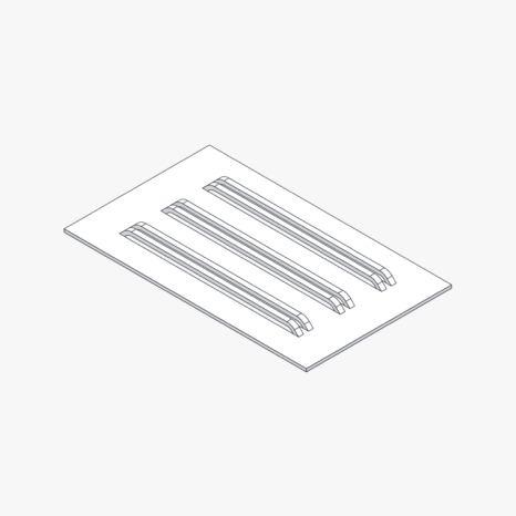
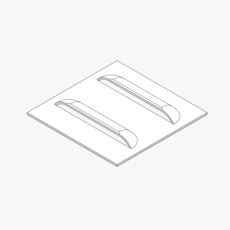
Stocked Bridge Lance Tools
A bridge lance feature is a raised, bridge-like structure formed by partially cutting and then bending the metal, which provides reinforcement, allows for airflow, or facilitates fastening without additional components. Click on the tabs below to see what features are stocked for available material thicknesses.
| Name | Station | Width | Length | Height |
|---|---|---|---|---|
| BL11 | B(1-1/4) | 0.25 | 0.72 | 0.2 |
| BL12 | B(1-1/4) | 0.079 | 0.437 | 0.118 |
| BL13 | B(1-1/4) | 0.154 | 0.669 | 0.157 |
| Name | Station | Width | Length | Height |
|---|---|---|---|---|
| BL21 | B(1-1/4) | 0.118 | 0.542 | 0.173 |
| Name | Station | Width | Length | Height |
|---|---|---|---|---|
| BL31 | B(1-1/4) | 0.125 | 0.275 | 0.173 |
| BL32 | B(1-1/4) | 0.15 | 0.58 | 0.13 |
| BL33 | B(1-1/4) | 0.25 | 0.285 (flat) | 0.071 (opening) |
| BL34 | B(1-1/4) | 0.125 | 0.526 | 0.188 |
| BL35 | B(1-1/4) | 0.276 | 0.737 | 0.157 |
| BL36 | B(1-1/4) | 0.157 | 0.583 | 0.138 |
| BL37 | C(2) | 0.394 | 1.348 | 0.197 |
| Name | Station | Width | Length | Height |
|---|---|---|---|---|
| BL51 | B(1-1/4) | 0.075 | .361 Flat | 0.175 |
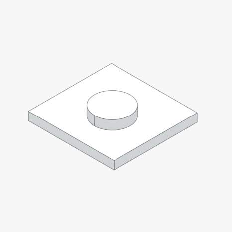
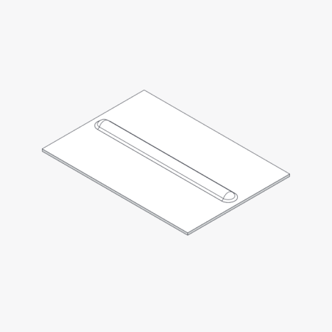
Stocked Dimple/Emboss Tools
An emboss feature is a raised or recessed design stamped into the material to add rigidity, create decorative elements, or provide functional enhancements such as grip or alignment features. A dimple feature is the same as an emboss feature, just at smaller dimensions.
Download dimple and emboss CAD files:
Emboss ToolsDimple Tools

Emboss Tools
| Name | Station | X-axis | Y-axis | Height |
|---|---|---|---|---|
| EB11 | B(1-1/4) | 0.5 | 0.563 | 0.089 |
| EB12 | C(2) | 1.56 | 0.69 | 0.067 |
| EB13 | C(2) | .375 Flat | 0.167 | |
| EB14 | B(1-1/4) | .210 Flat | .157 | |
| EB15 | C(2) | .983 Flat | .483 Flat | 0.2 |
| EB16 | B(1-1/4) | .54 Flat | 0.07 |
*if an emboss tool has an X dimension shown, it is a non-round feature (e.g. obround or square)
| Name | Station | Y-axis | Height |
|---|---|---|---|
| EB21 | C(2) | .706 Flat | 0.1 |
| EB22 | C(2) | .500 Flat | 0.179 |
| EB23 | D(3-1/2) | .750 Flat | 0.34 |
| EB24 | B(1-1/4) | .375 Flat | 0.1 |
| EB25 | B(1-1/4) | 0.458 Flat | 0.037 |
| Name | Station | X-axis | Y-axis | Height |
|---|---|---|---|---|
| EB31 | C(2) | .628 Flat | 0.209 | |
| EB32 | C(2) | 1.00 Flat | .300 Fat | 0.17 |
| EB33 | B(1-1/4) | 0.49 Flat | 0.065 | |
| EB34 | B(1-1/4) | .28 Flat | 0.07 |
*if an emboss tool has an X dimension shown, it is a non-round feature (e.g. obround or square)
| Name | Station | X | Y | H |
|---|---|---|---|---|
| EB41 | C(2) | 1.161 | 0.768 | 0.118 |
| EB42 | C(2) | 0.984 Flat | 0.315 | |
| EB43 | B(1-1/4) | .421 Flat | 0.146 | |
| EB44 | B(1-1/4) | .550 Flat | .354 Flat | 0.108 |
*if an emboss tool has an X dimension shown, it is a non-round feature (e.g. obround or square)
| Name | Station | Y | H |
|---|---|---|---|
| EB51 | B(1-1/4) | .473 Flat | 0.2 |
| EB52 | B(1-1/4) | 0.375 | 0.028 |
| EB53 | C(2) | 1.188 Flat | 0.2 |
| Name | Station | Y | H |
|---|---|---|---|
| EB61 | B(1-1/4) | .245 Flat | 0.1 |
| EB62 | B(1-1/4) | .512 Flat | .106 |
| Name | Station | Y | H |
|---|---|---|---|
| EB71 | C(2) | 1.000 Flat | 0.11 |
| EB72 | C(2) | 1.106 | 0.15 |
Dimple Tools
| Name | Station | Depth | Height |
|---|---|---|---|
| D11 | B(1-1/4) | 0.145 | 0.02 |
| D12 | B(1-1/4) | 0.456 | 0.096 |
| D13 | B(1-1/4) | 0.157 | 0.098 |
| D14 | B(1-1/4) | 0.153 | 0.026 |
| Name | Station | Depth | Height |
|---|---|---|---|
| D41 | B(1-1/4) | .070 Flat | 0.03 |
| D42 | A(1/2) | 0.181 | 0.041 |
| Name | Station | Internal Diameter | Height |
|---|---|---|---|
| EX11 | B(1-1/4) | 0.098 | 0.036 |
| EX12 | B(1-1/4) | 0.130 | 0.039 |
| EX13 | B(1-1/4) | 0.087 | 0.04 |
| Name | Station | Internal Diameter | Height |
|---|---|---|---|
| EX21 | B(1-1/4) | 0.136 | 0.082 |
| EX22 | B(1-14) | 0.106 | 0.053 |
| Name | Station | Internal Diameter | Height |
|---|---|---|---|
| EX31 | B(1-1/4) | 0.145 | 0.136 |
| EX32 | B(1-1/4) | 0.283 | 0.14 |
| Name | Station | Internal Diameter | Height |
|---|---|---|---|
| EX41 | B(1-1/4) | 0.213 | 0.083 |
| Name | Station | Internal Diameter | Height |
|---|---|---|---|
| EX61 | B(1-1/4) | 0.236 | 0.102 |
| EX62 | B(1-1/4) | 0.22 | 0.106 |
| Name | Station | Diameter | Height |
|---|---|---|---|
| HS11 | B(1-1/4) | 0.059 | 0.018 |
| Name | Station | Diameter | Height |
|---|---|---|---|
| HS21 | B(1-1/4) | 0.188 | 0.03 |
| Name | Station | Diameter | Height |
|---|---|---|---|
| HS61 | B(1-1/4) | 0.157 | 0.052 |
| Name | Station | Diameter | Height |
|---|---|---|---|
| HS71 | B(1-1/4) | 0.236 | 0.06 |
| HS72 | B(1-1/4) | 0.055 | 0.06 |
| HS73 | B(1-1/4) | 0.228 | 0.06 |
| HS74 | B(1-1/4) | 0.25 | 0.06 |
| HS75 | B(1-1/4) | 0.163 | 0.06 |
| Name | Station | Width | Depth | Height |
|---|---|---|---|---|
| L11 | D(3-1/2) | 2.06 | 0.48 | 0.24 |
| L12 | D(3-1/2) | 2.732 | 0.488 | 0.24 |
| L13 | B(1-1/4) | 0.5 | 0.111 | 0.059 |
| Name | Station | Width | Depth | Height |
|---|---|---|---|---|
| L21 | D(3-1/2) | 2.06 | 0.48 | 0.24 |
| Name | Station | Width | Depth | Height |
|---|---|---|---|---|
| L31 | D(3-1/2) | 1.12 | 0.48 | 0.24 |
| L32 | D(3-1/2) | 2.06 | 0.48 | 0.24 |
| Name | Station | Width | Depth | Height |
|---|---|---|---|---|
| L41 | D(3-1/2) | 2.06 | 0.48 | 0.24 |
| Name | Station | Width | Depth | Height |
|---|---|---|---|---|
| L51 | D(3-1/2) | 2.06 | 0.48 | 0.24 |
| Name | Station | Width | Depth | Height |
|---|---|---|---|---|
| L61 | D(3-1/2) | 2.06 min | 0.625 | 0.25 |
| Name | Station | Width | Depth | Height |
|---|---|---|---|---|
| L71 | D(3-1/2) | 2.5 min | 0.49 | 0.34 |
| Name | Station | Width | Length | Height |
|---|---|---|---|---|
| R11 | B(1-1/4) | 0.207 | .438 min | 0.035 |
| R12 | B(1-1/4) | 0.246 | .425 min | 0.05 |
| R13 | B(1-1/4) | 0.375 | .700 min | 0.1 |
| R14 | B(1-1/4) | 0.246 | 0.746 | 0.059 |
| R15 | B(1-1/4) | 0.108 | .401 min | 0.04 |
| Name | Station | Width | Length | Height |
|---|---|---|---|---|
| R21 | B(1-1/4) | 0.177 | .453 min | 0.039 |
| R22 | C(2) | 0.562 Flat | .900 min | 0.098 |
| R23 | B(1-1/4) | 0.457 | .700 min | 0.182 |
| Name | Station | Width | Length | Height |
|---|---|---|---|---|
| R31 | B(1-1/4) | 0.182 | 0.407 min | 0.045 |
| R32 | B(1-1/4) | 0.482 | 0.700 min | 0.182 |
| R33 | B(1-1/4) | 0.135 | 0.4 | 0.03 |
| R34 | C(2) | 0.731 | 0.803 min | 0.126 |
| R35 | B(1-1/4) | 0.362 | 0.454 min | 0.059 |
| Name | Station | Width | Length | Height |
|---|---|---|---|---|
| R41 | B(1-1/4) | 0.3 | 0.627 min | 0.135 |
| R42 | C(2) | 0.394 | 1.022 min | 0.201 |
| Name | Station | Width | Length | Height |
|---|---|---|---|---|
| R51 | B(1-1/4) | 0.29 | .536 min | 0.079 |
| R52 | B(1-1/4) | 0.214 | .464 min | 0.062 |
| R53 | B(1-1/4) | 0.525 | .700 min | 0.182 |
| Name | Station | Width | Length | Height |
|---|---|---|---|---|
| R71 | B(1-1/4) | 0.511 | .700 min | 0.187 |