


Solving Wall Thickness Issues in Molded Parts
Navigate common manufacturing advisories in your quote's design analysis with tips to help avoid wall thickness red flags
It seems there’s some truth to the Goldilocks story, at least when it comes to plastic injection-molded part design. That’s because several potential problems related to feature thickness exist, some of which can be avoided by shooting for a “just right” dimensional value, and others by optimizing your design for machinability by a specific set of tools (or endmills) used to machine your mold cavity.
All parts submitted to our advanced quoting system get DFM (design for manufacturing) feedback and advisories, but what if some of those advisories require some remedial design work? No worries! Those advisories provide the info you need to create high quality parts with us, quickly and accurately. This design tip offers up details on some of the most common advisories and helps you move forward before your mold is made and production begins.
Required Change: Thick Area
Sink marks, internal voids, excessive shrink, warp, and dimensional inaccuracies are likely.
Before diving into the nitty gritty, let’s discuss some quick review around nominal thickness of your part design, and what affects that might have on the final molded part. As noted above, improper wall thickness can lead to a host of problems. Very thick parts will lead to cosmetic and structural problems like voiding and warping, while very thin parts may reduce structural strength, or not fill at all. You certainly don’t want that, but even more importantly, walls that are too thick or too thin will make the part un-moldable. As a best practice, it is always critical to design your part for the recommended wall thickness of the material and maintain a consistent wall thickness throughout your part.
Recommended Wall Thickness by Plastic Type
|
MATERIAL |
RECOMMENDED WALL THICKNESS |
|---|---|
|
ABS |
0.045 in.-0.140 in. (1.143-3.556mm) |
|
Acetal |
0.030 in.-0.120 in. (0.762-3.048mm) |
|
Acrylic |
0.025 in.-0.500 in. (0.635-12.7mm) |
|
Liquid crystal polymer |
0.030 in.-0.120 in. (0.762-3.048mm) |
|
Long-fiber reinforced plastics |
0.075 in.-1.000 in. (1.905-25.4mm) |
|
Nylon |
0.030 in.-0.115 in. (0.762-2.921mm) |
|
Polycarbonate |
0.040 in.-0.150 in. (1.016-3.81mm) |
|
Polyester |
0.025 in.-0.125 in. (0.635-3.175mm) |
|
Polyethylene |
0.030 in.-0.200 in. (0.762-5.08mm) |
|
Polyphenylene sulfide |
0.020 in.-0.180 in. (0.508-4.572mm) |
|
Polypropylene |
0.025 in.-0.150 in. (0.635-3.81mm) |
|
Polystyrene |
0.035 in.-0.150 in. (0.889-3.81mm) |
|
Polyurethane |
0.080 in.-0.750 in. (2.032-19.05mm) |
Now on to the fun stuff: machinability. We use a proprietary, automated process to manufacture our molds to accelerate the process. We use standardization and machine connectivity from the time that you upload your part, to the time that the finished part leaves our facility. Standardization drives our speed, but it does come with a tradeoff for product developers optimizing a part for our process: Sometimes we can’t machine your part exactly as you designed it. Here are the common machinability advisories, as well as resolution strategies to ensure that your part design is manufacturable, and you get it fast.
Draft Suggestion
The areas indicated show faces with insufficient draft. We suggest a minimum of 1 degree draft in order to avoid possible cosmetic defects during milling and ejection.
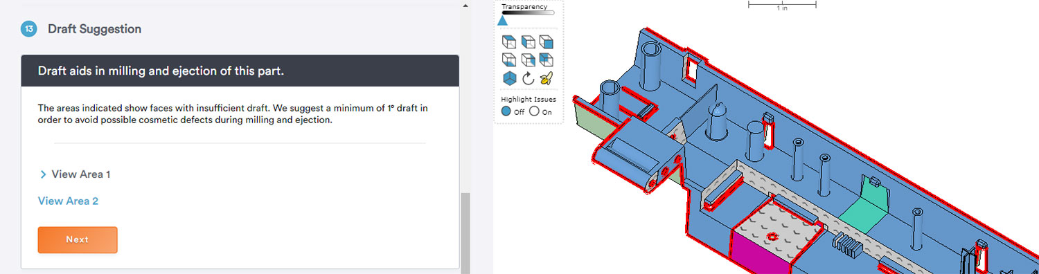
Draft is a fundamental element of DFM, and if you’re not familiar with the concept, you can come up to speed quickly with this design tip. In this case, the required change is likely driven by one of two things:
- EJECTION: Vertical walls that are not drafted will generally increase retention against the geometry forming feature in the mold. This means it will be really had to eject the part without creating scratches and scuffs known as “drag marks.” Worse yet, the increased retention could make the part stick into the mold, and bend or break ejector pins. For this reason, it is always best practice to include AT LEAST 0.5 degrees of draft on all vertical faces. In this example, however, we have another challenge.
- MACHINABILITY: The “faces with arrows” described in the required change are located on a deep boss and are all at roughly the same depth. This is a good indicator that the features can be machined but would require additional draft or thickness—not to facilitate ejection—but rather to ensure that we can fit an endmill into the feature to mill it fully.
SPOTLIGHT ON ENDMILLS
At Protolabs, we use a standardized endmill toolset to machine your mold cavity. In all, there are about 150 tools in various diameters and depths. Some tools are also drafted to add strength to the tool, which is generally dictated by its depth. In general, shallow features can often be machined by zero degree cutters, while mid-depth features will be machined by cutters in the 0.5 to 1.0 degree draft range. For deep features, we may require up to 2.0 degrees of draft.
Required Change: Minimum Thickness
Your part has thin features that need to be increased in thickness to the minimum indicated by the color code.
Earlier, we talked about how some required changes are driven by the thickness needed to maintain machinability. In this case, the BLUE wall faces are less than 0.020 in. (0.508mm) in thickness. To machine this feature, we need to use our smallest endmill. The thinnest feature that we’re able machine is 0.020 in. (0.508mm), so to resolve this change, you would just need to increase the thickness of the circular features to a minimum of 0.020 in. (0.508mm).
Required Change: Draft and Thickness
0.5° minimum draft is required on faces with arrows. Arrows indicate the pull direction for faces in the mold.
Unsurprisingly, draft and thickness are exactly what you think. If you recall our tip on types of endmills, many of them require draft in order to mill a feature of a certain depth. In the case of a draft and thickness requirement, the feature thickness must be increased to fit the tool diameter required to mill it, but the vertical faces on the feature must also be drafted to facilitate the draft angle of the cutter. These required changes are most common on features that are both thin and deep.
One thing to note: We do have some flexibility when it comes to required changes for draft and thickness. Specifically, we can reduce the draft needed in exchange for a higher thickness requirement, and vice versa. Review those possibilities with one of our applications engineers to see if your part would qualify.
Required Change: Thin Slot
This feature needs to be at least 0.040 in. (1.0mm) wide at the base to withstand the stresses of the manufacturing process.
Thin slots are blade-like pieces of milled aluminum in the mold required to form slotted features in a part. It is important to remember that the mold cavity is the exact inverse of the geometry on your part. So, a thin slot or channel in the part geometry will require a thin piece of aluminum in the mold, often standing on its own, unsupported. This becomes a challenge due to the stresses of the manufacturing process itself. Think of a piece of aluminum roughly similar to the blade of a butter knife. Now imagine adding up to 14,000 psi of pressure to that blade. Do you think it would flex, bend, or break? This is the same premise that we’re up against when molding with thin slots. The freestanding blade-like aluminum is prone to deflection (flexing and bending) and in some cases even breaking off completely, which means we need to cut a new mold.
Resolving this required change is easy. Simply increase the slot width of the feature, thus increasing the thickness of the aluminum that will form it in the mold.
Navigating Thin Slots in Molding Design
|
How Quickly to Open Up |
||||
|---|---|---|---|---|
|
Slot Min |
Ratio @ 0° |
Ratio @ 0.5° |
Ratio @ 1-2° |
Ratio @ 2°+ |
|
0-0.01 in. (0-0.254mm) |
1:1 |
1:1 |
2:1 |
4:1 |
|
0.01-0.02 in. (0.254-0.508mm) |
1:1 |
2:1 |
4:1 |
8:1 |
|
0.02-0.03 in. (0.508-0.762mm) |
2:1 |
4:1 |
5:1 |
10:1 |
|
0.03-0.04 in. (0.762-1.016mm) |
2:1 |
5:1 |
8:1 |
15:1 |
|
0.04-0.06 in. (1.016-1.524mm) |
4:1 |
8:1 |
10:1 |
20-1 |
|
0.06 in. + (1.524mm +) |
5:1 |
10:1 |
15:1 |
25-1 |
Note: Double all ratios if captured on three sides
Remember, required changes and molding advisories are a critical step to making your part moldable. Hopefully these tips on some of the most common ones will help guide you past them and keep your parts on schedule. If you have any questions, don’t hesitate to contact our applications engineers for help at 877-479-3680 or [email protected].


