


What is Design for Additive Manufacturing?
Rapid advances in 3D printing technologies suggest it’s important to take a step back and keep yourself focused on the rules behind manufacturing printed parts
Design for additive manufacturing (DFAM) is a collection of rules and best practices that designers and engineers must follow to achieve high levels of success in printed part designs. Additive manufacturing (AM), known commonly as 3D printing (3DP), encompasses multiple technologies, such as stereolithography (SLA), selective laser sintering (SLS), fused deposition modeling (FDM), direct metal laser sintering (DMLS), and others. DFAM incorporates considerations involving the chosen technology to print your parts, part geometry, materials used, and any post-processing steps needed to strengthen or improve the look of your parts. And always, there are cost considerations. Depending on how you design your part, it could be exceedingly expensive, or cost-effective.
Central to this discussion is ensuring a design’s printability. 3DP has the reputation of being the Wild West when it comes to manufacturing design—anything goes there—but that’s not true. Just as with molding, machining, or sheet metal fabrication, there are design limitations that, if not considered, will cause part failures during build, or worse, during end-use. But that said, 3DP does offer a wider range of complex geometric possibilities than any other standard manufacturing process. It can also prove to be a time-saver when compared to parts that once had to undergo multiple processes to complete.
When manufacturing complex parts, 3D printing is often the best choice because it:
- Requires no molds or other expensive tooling
- Offers considerable geometric flexibility and customization
- Has only limited material waste (you essentially pay only for the material required to make your part)
Key Concepts and Approaches to Designing for Additive Manufacturing
DFAM incorporates tools and processes that go beyond simply ensuring your part is printable. Let’s start with some key 3D printing terms that are truly crucial to understanding how it will benefit you as a designer:
Generative Design
This process uses artificial intelligence (AI) to create and iterate designs that meet a given set of input criteria for an application. The goal is to achieve design efficiencies that can help:
- Create lighter, stronger, and more efficient designs
- Reduce part costs
- Enhance sustainability
- Increase performance
- Improve innovation
While still in the early phases of development, generative design offers tremendous potential for rapid part iteration and is fundamental to the future of DFAM.
Part Consolidation
A commonly cited benefit of additive manufacturing is the ability to consolidate multiple parts into a single one. One notable example is GE’s additively manufactured fuel nozzle for CFM International’s LEAP aircraft engine. The nozzle was an engine component made from 20 parts. Now, it’s one part, with the bonus of a 25% weight reduction. Having one part do the work of multiple parts can trim inventory, reduce labor costs for assembly, simplify construction of your product, and even lightweight your parts.
Topology Optimization
This strategy is all about discovering the optimal distribution of material to maintain crucial specifications for a part, such as weight, stiffness, and strength. Often a part can be 3D printed with a special internal structure that maintains strength but reduces weight by using less material. For example, imagine aircraft parts that can be designed to be half the weight of a fully solid part, but remain strong. The reduced aircraft weight can save an airline on fuel costs.

Cost Factors in 3D Printing
Ultimately, price is based on choice of material, build time, volume of parts needed, post-processing, and more. You can design intricate geometries, but complexity is time-consuming and costly. Also, consider that strong parts can be built with minimal interior structure, saving time and money. Need more details? Check out our design tip on cutting costs.
Read Design TipDesign Guidelines for Additive Manufacturing
A few of the most crucial DFAM considerations make a lot of sense if you think about them a bit. Let’s tick them down, one by one.
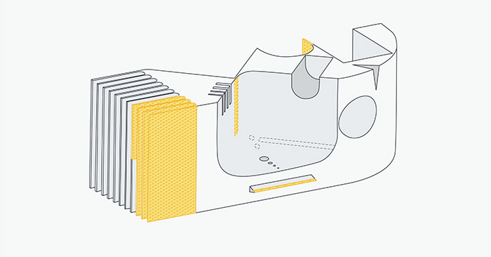
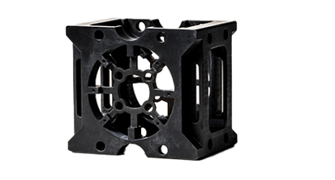
This drawing of the part rendered above reveals the difficulty of designing tall walls and other special features using 3D printing.
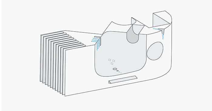
Small gaps in features also pose difficulties for 3D printing. Plastic is affected by gravity and wants to sag or warp, given the chance. While these features are possible, check with us if you are concerned about your CAD model's DFAM-worthiness.
Wall thickness
Make your walls too thick and you’ll add time and cost to your parts, and while thin walls have a great look, they can also look awful when they crack off during end-use. Thin walls may not have enough strength to withstand forces or stresses during use and may deform or break easily. Potentially, they can cause warp, or layers may separate during printing. In the end, you may end up with a rough surface finish due to poor bonding between layers and may even have difficulties printing a part if walls are too thin. In truth, wall thickness comes down to the material and manufacturing process you choose.
A great example is that if you need thin walls in your designs for DMLS parts, use the 40:1 rule of height-to-wall thickness. For example, if you have a 0.1 in. (2.54mm) thick wall, the wall height shouldn’t be more than 4 in. (101.6mm) to maintain structural integrity. However, that 40:1 rule can be stretched a bit if the wall is more naturally self-stabilizing, like the wall of a cylinder.
Minimum feature size
Each printing process offers different capabilities to print small features. If you stay within these parameters, you should be in fairly good shape with your design.
| Process | Minimum Feature Size |
| SLA | 0.0025 in. (0.0635mm) |
| DMLS | 0.006 in. (0.153mm) |
| FDM: Desktop | 0.008 in. (0.2mm) |
| FDM: Industrial | 0.008 in. (0.2mm) |
| PolyJet | 0.012 in. (0.305mm) |
| Carbon DLS | 0.020 in. (0.508mm) |
| MJF | 0.020 in. (0.508mm) |
| SLS | 0.030 in. (0.762mm) |
Self-supporting angles
Building a part layer-by-layer requires that you consider the law of gravity in your design. Heavy areas tend to sag and warp as parts are built, so you want to ensure that any feature can support its own weight during the build by using smooth transitions to control potential sag.
Metal 3D printing has its own set of design issues, yet one common item that emerges involves overhangs. Different from self-supporting angles that offer a smooth slope to a part design, overhangs are abrupt changes in a part’s geometry. DMLS is fairly limited in its support of overhangs when compared to other 3D printing technologies like SLA and SLS. Any overhang greater than 0.020 in. (0.5mm) should have additional support to prevent damage to the part during the build. When designing overhangs, it is wise to not push the limits as large ones can cause a reduction in a part’s detail or worse, lead to the whole build crashing.
Internal channels
Keep in mind that it is very difficult, if not impossible, to replicate the complexity of an internal channel in other manufacturing processes, so if you add these features, verify that moving to another process, like injection molding for example, would be possible before going down a rabbit hole. That said, when designing internal channels, consider the rules you normally associate with design for 3D printing, especially strategies behind printing overhangs and minimum feature size. If you intend to flow fluids through these channels, you’ll need a very smooth (high resolution) print. FDM is a good choice for printing channels, compared to SLA. Find the process that will give you the best quality print, but if you end up with rough internal channels, there are post-processing techniques that can help improve the texture.
Note that internal channels do cost more and take longer to print due to the complexity of each part.
Part orientation
Does it matter from what side you start to print a part? Yes! Some directions are more efficient than others and may improve strength and build quality. Determining what should be the Z axis—the one in which the part grows up from—turns out to be crucial. In fact, it can even play a role in manufacturing speed and cost.
While the build depends on the process you choose (e.g., SLA, DMLS), the idea is the same. The printer “draws” a thin layer of material, and it cures a bit before the next layer is added. You want that to happen in a way that avoids challenging gravity because gravity always wins. A rule to remember is that if a part must endure a compressive force, we will print it with the layers running parallel to the direction of the force.
Surface finish is also affected by part orientation during printing. For smooth parts, we print so that the layers are parallel to the part’s surface. If a process involves a build plate, it can act as a support that will provide a smooth surface finish to your parts.
Cost is an additional consideration. The fewer support structures and infills included, the less expensive the part. We try to orient the part in a way that doesn’t challenge gravity, to try to remove time and material from the build.

Moving from AM to IM
When transitioning your part to injection molding, remember to adjust part geometries to address injection molding’s DFM rules, and some design elements might not transition at all. Also, think about how material will flow through a mold to ensure sharp corners get filled. Finally, don’t forget that adding draft is essential for molded parts.
Read MoreGetting DFAM Help
Desiging for 3D printing can sometimes look easy at first glance, but doing it efficiently means following the rules of DFAM. Feel free to contact us with any questions at 877-479-3680 or [email protected]. Our applications engineers can help guide you toward a successful printed part.