


Design Guidelines: Plastic Injection Molding
Our basic guidelines for plastic injection molding include important design considerations to help improve part moldability, enhance cosmetic appearance, and reduce overall production time.
Size
Maximum Dimensions
| SIZE | 18.9 in. x 29.6 in. x 8 in. |
|---|---|
| VOLUME | 59 cu. in. |
| DEPTH | 4 in. from parting line |
| Up to 8 in. if parting line can pass through the middle of the part | |
| PROJECTED MOLD AREA | 175 sq. in. |
| SIZE | 480mm x 751mm |
|---|---|
| VOLUME | 966,837 cu. mm |
|
DEPTH |
101mm from parting line |
| Up to 203.2mm if the parting line can pass through the middle of the part | |
| PROJECTED MOLD AREA | 112,903 sq. mm |
Typically, Protolabs can maintain a machining tolerance of +/- 0.003 in. (0.08mm) with an included resin tolerance that can be greater than but no less than +/- 0.002 in./in. (0.002mm/mm).

Materials
- ABS
- ABS/PC
- Acetal
- Acetal Copolymer
- Acetal Homopolymer
- ETPU
- HDPE
- LCP
- LDPE
- LLDPE
- Nylon 6
- Nylon 5/12
- PBT
- PC/PBT
- PEEK
- PEI
- PET
- PETG
- PMMA
- Polycarbonate
- Polypropylene
- PPA
- PPE/PS
- PS
Surface Finishes
| FINISH | DESCRIPTION |
|---|---|
| PM-F0 | non-cosmetic, finish to Protolabs' discretion |
| PM-F1 | low-cosmetic, most toolmarks removed |
| PM-F2 | non-cosmetic, EDM permissible |
| SPI-C1 | 600 grit stone, 10-12 Ra |
| PM-T1 | SPI-C1 + light bead blast |
| PM-T2 | SPI-C1 + medium bead blast |
| SPI-B1 | 600 grit paper, 2-3 Ra |
| SPI-A2 | grade #2 diamond buff, 1-2 Ra |
Mold texturing applies industry standard textures to a mold and you can expect the equivalent of a Mold-Tech finish.
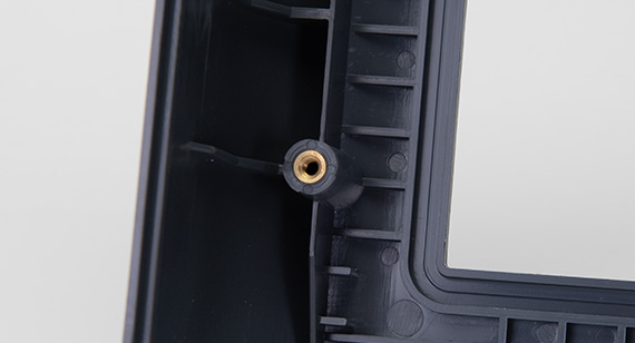
Threaded inserts are possible through secondary heat staking and ultrasonic welding processes. A complete chart of stocked inserts is available here.
Pad printing transfers a two-dimensional image like company logos onto a three-dimensional object.
Laser engraving is applied to the mold or directly to final parts for information such as part numbers.
Basic assembly includes fastening molded parts together that we’ve manufactured and/or applying of labels to individually bagged parts.


Draft
| VERTICAL FACES |
0.5° |
|---|---|
| MOST SITUATIONS |
2° |
| MINIMUM FOR SHUT OFF | 3° |
| MINIMUM FOR LIGHT TEXTURE (PM-T1) | 3° |
| MINIMUM FOR LIGHT TEXTURE (PM-T2) | 5°+ |
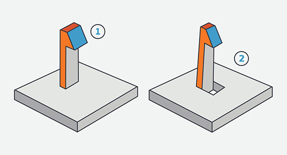
Undercuts
Maximum Side Core Dimensions
| WIDTH | HEIGHT | PULL |
|---|---|---|
| < 8.419 in. | < 2.377 in. | < 2.875 in. |
Maximum Side Core Dimensions
| WIDTH | HEIGHT |
PULL |
|---|---|---|
| < 213.84mm | < 60.38mm | < 73.66mm |
Wall Thickness
| MATERIAL | RECOMMENDED WALL THICKNESS |
|---|---|
| ABS | 0.045 in. - 0.140 in. |
| Acetal | 0.030 in. - 0.120 in. |
| Acrylic | 0.025 in. - 0.500 in. |
| Liquid Crystal Polymer | 0.030 in. - 0.120 in. |
| Long-Fiber Reinforced Plastics | 0.075 in. - 1.000 in. |
| Nylon | 0.030 in. - 0.115 in. |
| Polycarbonate | 0.040 in. - 0.150 in. |
| Polyester | 0.025 in. - 0.125 in. |
| Polyethylene | 0.030 in. - 0.200 in. |
| Polyphenylene Sulfide | 0.020 in. - 0.180 in. |
| Polypropylene | 0.035 in. - 0.150 in. |
| Polystyrene | 0.035 in. - 0.150 in. |
| Polyurethane | 0.080 in. - 0.750 in. |
Table is adapted from manufacturingcenter.com.
| MATERIAL |
RECOMMENDED WALL THICKNESS |
|---|---|
|
ABS |
1.143mm - 3.556mm |
| Acetal |
0.762mm - 3.048mm |
| Acrylic | 0.635mm - 12.7mm |
| Liquid Crystal Polymer | 0.762mm - 3.048mm |
| Long-Fiber Reinforced Plastics | 1.905mm - 25.4mm |
| Nylon | 0.762mm - 2.921mm |
| Polycarbonate | 1.016mm - 3.81mm |
| Polyester | 0.635mm - 3.175mm |
| Polyethylene | 0.762mm - 5.08mm |
| Polyphenylene Sulfide | 0.508mm - 4.572mm |
| Polypropylene | 0.889mm - 3.81mm |
| Polystynene | 0.889mm - 3.81mm |
| Polyurethane | 2.032mm - 19.05mm |
Table is adapted from manufacturingcetner.com.
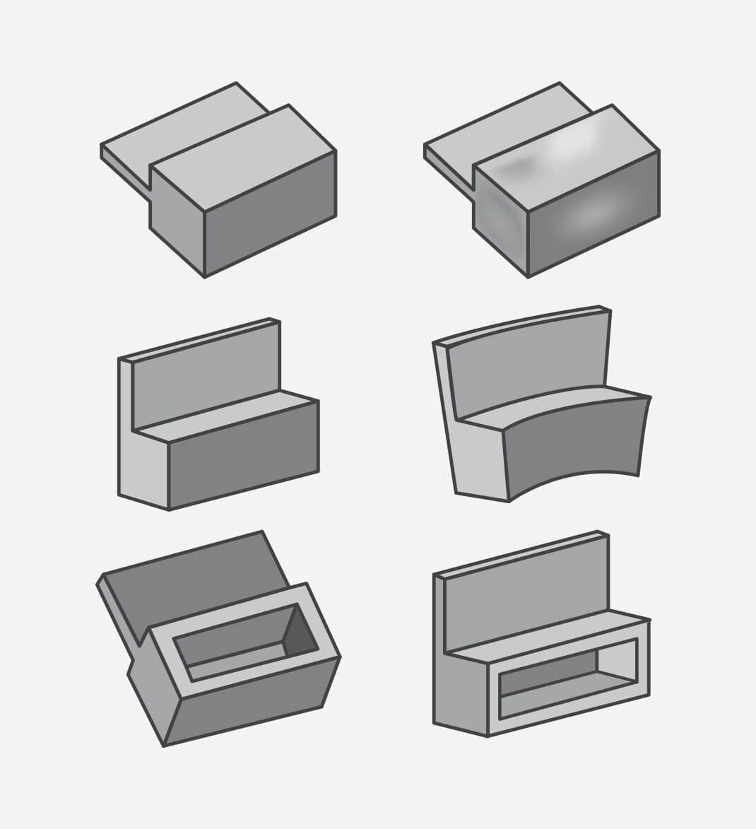
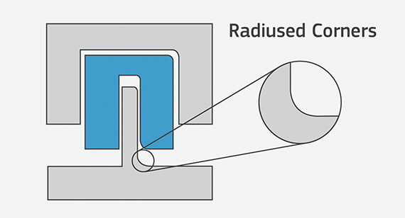
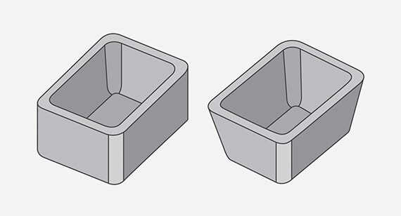
Radii
Some part corners will have a radius rather than a sharp edge since we use an automated CNC milling process to make the mold for your parts. This typically does not require a change to your model, but resulting radii are identified before the mold is milled.